A directional coupler is a crucial passive RF component used to sample a small portion of the signal from the main transmission path and direct it to one or more coupled ports. Due to its high isolation between the main path and the coupled port, directional couplers are known for their excellent port-to-port isolation. There are two primary types: standard directional couplers with a single coupled and terminated port, and dual directional couplers that have both forward and reverse coupled ports. Additionally, there are specialized versions like forward couplers and reverse couplers, which are designed based on whether they couple to the forward or reverse direction.
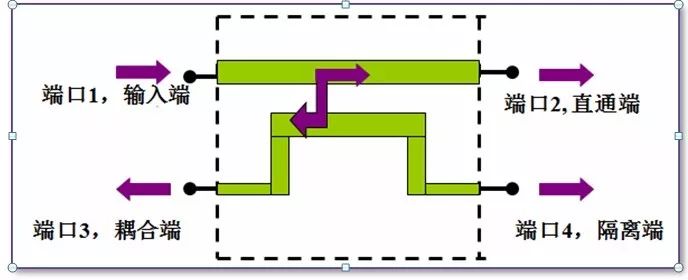
Common directional coupler schematic
One important aspect to consider is the coupling level, which directly affects the insertion loss in the main path. The lower the coupling, the smaller the insertion loss. However, the power rating of the coupled port is typically lower than that of the main path. If the power difference exceeds the coupled port’s capacity, it can lead to failure. A three-port directional coupler with internal termination is generally more directional than a four-port version using an external termination.
The type of termination at the unused port also plays a key role. When the termination resistor matches the characteristic impedance (usually 50 ohms), most of the energy is absorbed without reflection. But if the port is open, shorted, or mismatched, the reflected energy can interfere with the main path. This can be especially dangerous if the termination fails, causing destructive reflections within the system.
Directional couplers are widely used in test and measurement applications. For example, they can measure input and reflected power in a transmission line, helping determine the VSWR after accounting for coupler losses. They are also used for signal sampling, injection, and power monitoring, where understanding the coupler’s own loss is essential for accurate results.
When performing precise measurements, isolation between ports is critical. Even though some leakage is inevitable, this is measured as isolation. Directionality, defined as the ratio of isolation to coupling, is a key performance metric.
Like other RF components, directional couplers exhibit frequency-dependent behavior. Parameters such as coupling, insertion loss, and directivity vary with frequency. These variations, along with manufacturing tolerances, must be considered when making sensitive measurements. The operating bandwidth is another important factor, and design trade-offs are necessary to meet specific application requirements.
Most directional couplers block DC current due to grounded ports, although some models allow DC passage. For those that do, it's essential to keep current below rated levels to avoid overheating or performance issues. In dual or bidirectional couplers, all ports must be properly grounded, and the load should match the coupler’s impedance to ensure optimal performance.
Lastly, a 90-degree or 180-degree bridge is sometimes called a "coupler," but it operates differently from a traditional directional coupler. Though physically similar, these bridges distribute power (e.g., 3dB split) between output and coupling ports. Misidentifying them as low-coupling directional couplers can lead to improper use and potential damage.
Electronic Wire Harness,Double-Ended Terminal Wires,Quick Terminal Wire,Color Plate Wire
Dongguan ZhiChuangXing Electronics Co., LTD , https://www.zcxelectronics.com