
1. Control requirements
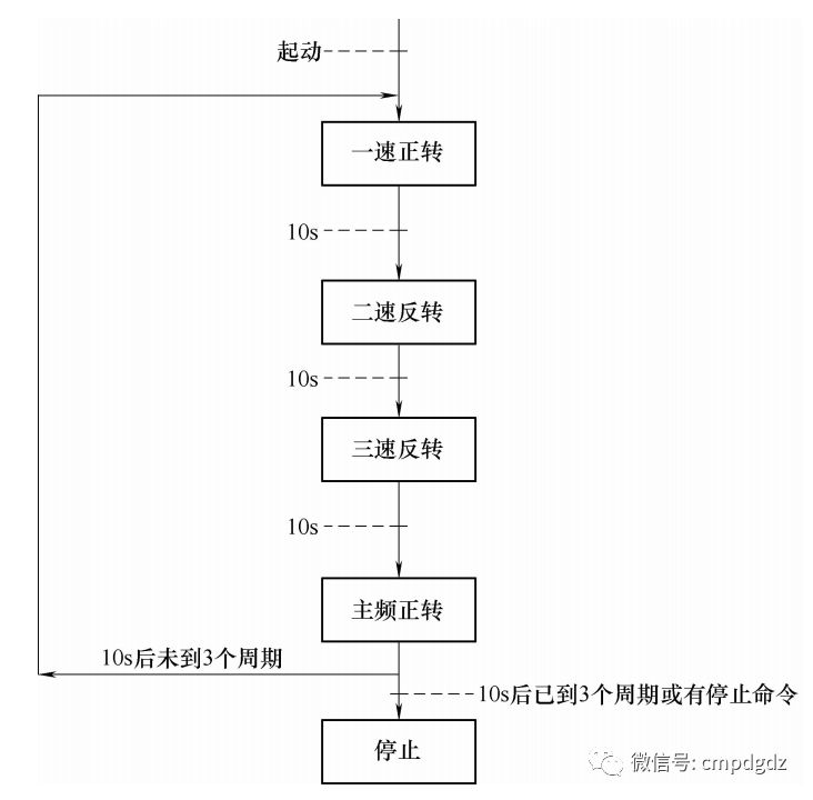
If there is no fault in the inverter and there is no emergency stop command in the console, after giving the start command, the inverter will act according to the sequence shown in the following figure. If a stop command is given on the way, it will stop at the end of the action cycle; if the inverter fails during the way or the emergency stop command is given on the console, it will stop immediately.
The actual running frequency of the inverter will be displayed on VW500. The main frequency of the inverter is given by the 0-10V analog value given by the PLC.
VFD-M Delta inverter parameter settings:
P00 = 01 P02 = 01 P17 = 10.0 P18 = 25.0 P19 = 40.0 P43 = 00 Other parameters are default values.
2. Control procedures
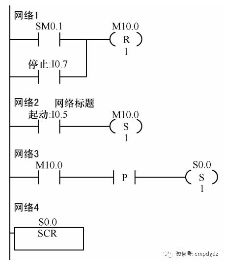
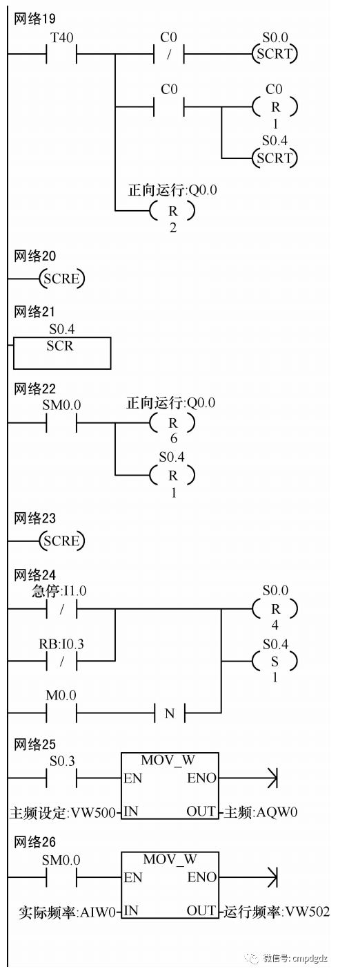
Explanation of program debugging:
M0.0 is the start flag, when M0.0 = 0 is the stop state, when M0.0 = 1 is the start state.
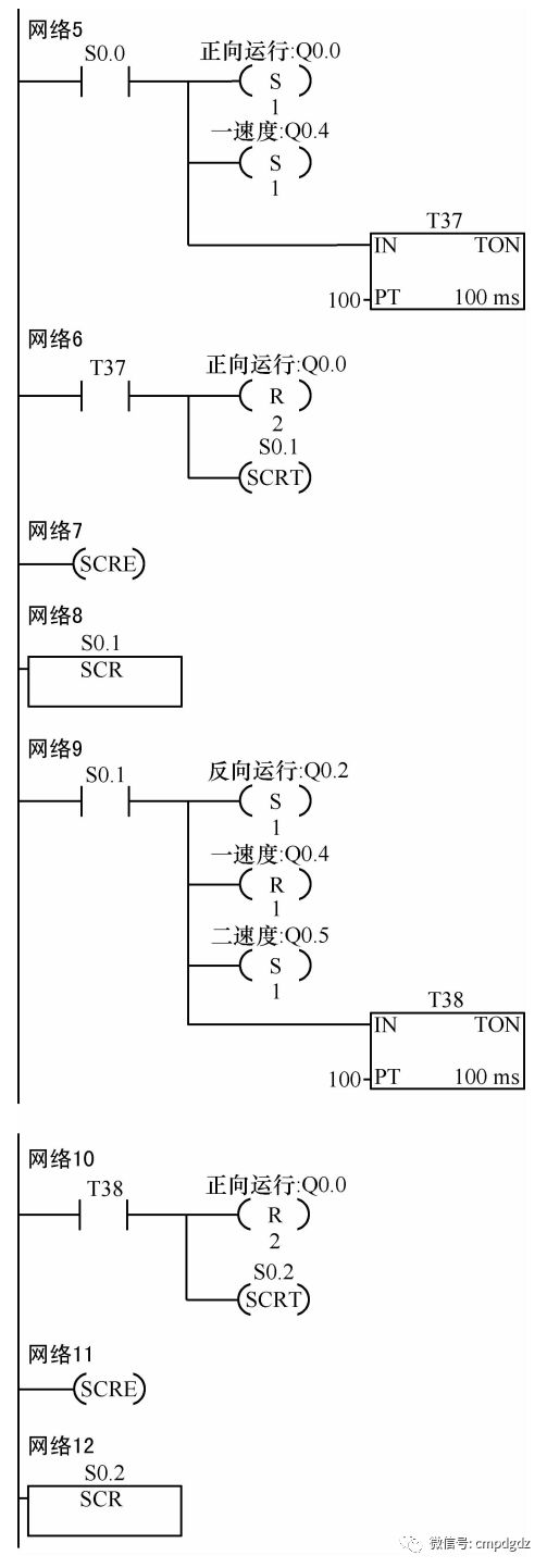
Step S0.0 controls the inverter to run in the forward direction at a speed of 10 Hz.
Step S0.1 controls the inverter to run in reverse at two speeds of 25 Hz.
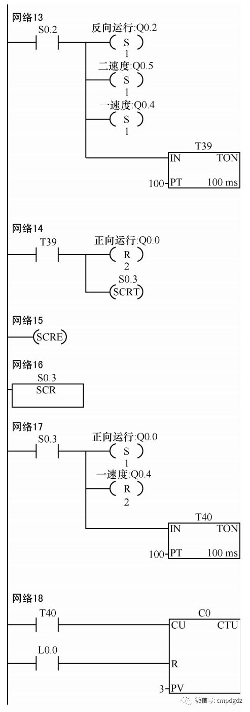
Step S0.2 controls the inverter to run in reverse at three speeds of 40 Hz.
Step S0.3 controls the inverter to run in the forward direction at the main frequency. The main frequency is given by the VW500 of the PLC. The VW500 value of 0 represents 0 Hz and the VW500 value of 32000 represents 60 Hz.
Step S0.4 controls the inverter to stop.
The actual running frequency of the inverter is collected by AIW0 to the PLC, and it comes out from VW502. The VW502 value of 0 represents 0 Hz operation, and the VW502 value of 32000 represents 60 Hz operation.
HDMI, known as High Definition Multimedia Interface, is mainly used for transmitting HD audio and video signals.
There are three types of data transmitted by HDMI TMDS (plus Hsync and Vsync count as four) :
1.Preamble (control information) is mainly used to control the Data to be transmitted next, namely Data Island or Video Data
2.Data Island, all kinds of packet information, including audio packet, image packet, etc
3.Video Data, Video pixel Data. HDMI can transmit pixel Data in RGB and YUV formats
4. And Hsync and Vsync
HDMI Source device (HDMI HPD) will monitor the Hotplug port of the sink device. If the Hotplug is High, it will prove that the device can work, and then read DCC; if it is low, it will prove that the device is disconnected.
The HDMI Sink device should notify the source device that EDID has been changed by pulling the Hotplug down, and the source device will read the new EDID again after the Hotplug is pulled up, which should be more than 100ms.
HDMI provides that the EDID can be read by DCC when the 5V pin of HDMI is powered on, that is, the Hotplug needs to be high, and some Hotplug is directly connected to the 5V
TMDS Clock is the Pixel Clock, the Clock frequency used for a Pixel point. Through TMDS Clock CLK pins transmitted to the receiver, but the receiver is not clear for what TMDS Clock frequency of the sender sent, so you need to through the Phy (Phy is analog to digital conversion section, is different from the ADC, Phy is don't know the sampling frequency, the need to lock frequency and phase lock, detect the exact input frequency) to lock.
Pc Hdmi Input,Hdmi Input Adapter,Hdmi Input Splitter,Hdmi Port On Tv
TONYA DISPLAY LIMITED , https://www.tydisplay.com