Video basics
At present, various video conference manufacturers at home and abroad have successively launched their own high-definition or ultra-clear products, and they are spared no effort to promote image resolution. However, to achieve high-definition / ultra-clear video conferencing, 720p or 1080p image resolution alone is not enough. Video conferencing is an application of multimedia. The entire system involves front-end video acquisition, image encoding capabilities, high-quality network transmission, and high-definition video display equipment. In addition, if we can't get a clearer, continuous audio effect when watching high-definition video images, then this process is actually meaningless, so high-quality audio is no less important than video. Therefore, there are a few key points of knowledge in high-definition or ultra-clear video conferencing: high-definition video resolution, high-definition video display device interface, high-quality audio transmission interface, high-quality audio. The development of technology is a gradual process. In this document, not only the related terms of high-definition video are listed, but also the related terms in non-high-definition video systems are listed together, so that there will be a very intuitive comparison process.
1 Video interfaceWe often see many video interfaces on the TV input and output interfaces of home TVs, various players, and codecs of video conferencing products and surveillance products. Which of these video interfaces are analog interfaces and which are digital interfaces? Which interfaces can transmit high-definition images, etc., a detailed introduction will be made below.
At present, the most basic video interfaces are composite video interface and S-vidio interface; in addition, there are color difference interface, VGA interface, DVI interface, HDMI interface and SDI interface.
1.1 Composite video interface 1.1.1 Interface diagram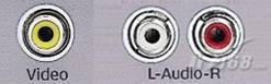
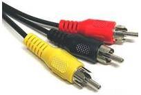
The composite video interface is also called the AV interface or the Video interface. It is currently the most common video interface. Almost all TV and DVD products have this interface.
It is a video interface with separate audio and video. It is generally composed of three independent RCA plugs (also known as plum blossom interfaces and RCA interfaces). The V interface is connected to the mixed video signal and is a yellow socket; the L interface is connected to the left channel sound The signal is a white socket; the R interface is connected to the right channel sound signal and is a red socket.
1.1.3 EvaluationIt is a mixed video signal, without RF modulation, amplification, detection, demodulation and other processes, the signal fidelity is relatively good. Image quality is greatly affected by the wire used, the resolution is generally up to 350-450 lines, but because it is an analog interface, when used in digital display devices, a process of converting an analog signal to a digital signal requires a lot of signal noise Than, so general digital display devices are not recommended.
1.2 S-Video interface 1.2.1 Interface diagram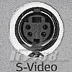


S interface is also a very common interface, its full name is Separate Video, also known as SUPER VIDEO. The S-Video connection specification is a specification developed by the Japanese. S refers to "SEPARATE (separation)", which separates the brightness and chrominance output, avoiding the mutual interference of brightness and chrominance when outputting mixed video signals. The S interface is actually a five-core interface, which is composed of five core wires including two apparent brightness signals, two video chrominance signals, and one common shielded ground wire.
1.2.3 EvaluationCompared with the AV interface, because it no longer performs Y / C mixed transmission, there is no need to perform bright color separation and decoding, and the use of separate transmission channels to a large extent avoids crosstalk caused by video equipment. The distortion of the image greatly improves the clarity of the image. However, S-Video still has to mix two color difference signals (Cr Cb) into one color signal C, transmit it, and then decode it into Cb and Cr for processing in the display device, which will still cause a certain signal loss. Distortion (This distortion is small but can still be found when tested under strict broadcast-grade video equipment). Moreover, due to the mixing of Cr Cb, the bandwidth of the chrominance signal is also limited, so although S-Video is already excellent, it is far from perfect. Although S-Video is not the best, it is still one of the most popular video interfaces considering the current market conditions and other factors such as comprehensive cost.
1.3 YPbPr / YCbCr color difference interface 1.3.1 Interface diagram
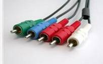
The color difference interface is based on the S interface, and the blue difference (b) and the red difference (r) in the chrominance (C) signal are sent separately, and the resolution can reach more than 600 lines. It usually uses YPbPr and YCbCr two kinds of signs, the former indicates progressive scan color difference output, the latter indicates interlaced scan color difference output. Many TV products now rely on color difference input to improve the quality of the input signal, and through the color difference interface, you can input multiple levels of signals, from the most basic 480i to 480p for double frequency scanning, even 720p, 1080i, etc. Only through the color difference input is there a way to transmit the signal to the TV.
1.3.3 EvaluationAccording to the relationship of TV signals, we only need to know the values ​​of Y, Cr, and Cb to get the value of G (green), so in the video output and color processing process, the green difference Cg is ignored and only Y Cr Cb is retained. This is the basic definition of color difference output. As an advanced product of S-Video, the color difference output decomposes the chrominance signal C transmitted by S-Video into the color difference Cr and Cb, thus avoiding the process of two-channel color difference mixing and decoding and separating again, and maintaining the chrominance channel The maximum bandwidth can be restored to RGB three primary color signals for imaging only through the inverse matrix decoding circuit, which minimizes the video signal channel from the video source to the display imaging, avoiding the burden of the cumbersome transmission process The incoming image is distorted, so the interface method of color difference output is currently one of the best analog video output interfaces.
1.4 VGA interface 1.4.1 Interface diagram
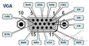
The VGA interface is also called the D-Sub interface. The VGA interface is a D-type interface with a total of 15 pins on it, divided into three rows of five. The VGA interface is the most widely used interface type on graphics cards, and most graphics cards have this type of interface. Mini audio or home theater with VGA interface can be easily connected to the computer monitor and use the computer monitor to display images.
1.4.3 EvaluationThe VGA interface still transmits analog signals. The display image information generated in a digital manner is converted into R, G, and B primary color signals and line and field synchronization signals by a digital / analog converter. The signals are transmitted to the display device through a cable. For an analog display device, such as an analog CRT display, the signal is directly sent to the corresponding processing circuit to drive and control the kinescope to generate an image. For digital display devices such as LCD and DLP, the corresponding A / D (analog / digital) converter needs to be configured in the display device to convert the analog signal into a digital signal. After the second conversion of D / A and A / D, it inevitably caused some loss of image details. It is understandable that the VGA interface is used in CRT monitors, but for display devices such as digital TVs, the image loss during the conversion process will slightly reduce the display effect.
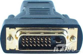
1.5 DVI interface 1.5.1 Interface diagramThe current DVI interface is divided into two types:
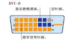

One is the DVI-D interface, which can only receive digital signals. There are only 24 pins in 3 rows and 8 columns on the interface, and one pin in the upper right corner is empty. Not compatible with analog signals.
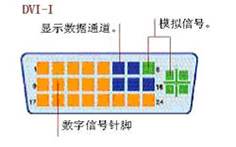
The other is the DVI-I interface, which is compatible with both analog and digital signals. Fortunately, analog compatibility does not mean that the analog signal interface D-Sub interface can be connected to the DVI-I interface, but it must be used through a conversion connector. Generally, graphics cards that use this interface will have related conversion connectors.
1.5.2 DescriptionDVI is called Digital Visual Interface. It was formed by Silicon Image, Intel (Intel), Compaq (Compaq), IBM, HP (HP), NEC, Fujitsu (Fujitsu) and other companies in 1999 to form DDWG (Digital Display Working Group, Digital Display Working Group) interface standard. It is based on Silicon Image ’s PanalLink interface technology and is based on TMDS (TransiTIon Minimized DifferenTIal Signaling) electronic protocol as the basic electrical connection. TMDS is a differential signal mechanism that can encode pixel data and pass it through a serial connection. The digital signal generated by the graphics card is encoded by the transmitter according to the TMDS protocol and sent to the receiver through the TMDS channel, and then sent to the digital display device after decoding. A DVI display system includes a transmitter and a receiver. The transmitter is the source of the signal, which can be built into the graphics card chip, or it can appear on the graphics card PCB in the form of an additional chip; and the receiver is a circuit on the display, which can receive digital signals, decode and transmit them In the digital display circuit, through these two, the signal sent by the graphics card becomes the image on the display.
1.5.3 Evaluation The display device using the DVI interface has the following two main advantages:
1. The fast speed DVI transmits digital signals. The digital image information will be directly transmitted to the display device without any conversion. Therefore, the tedious conversion process of digital → analog → digital is reduced, which greatly saves time, so it The speed is faster, the smear phenomenon is effectively eliminated, and DVI is used for data transmission, the signal is not attenuated, and the color is purer and more realistic.
2. The picture is clear. The computer internally transmits binary digital signals. If you use the VGA interface to connect to the LCD display, you need to first convert the signal into R, G, and B primary color signals through the D / A (digital / analog) converter in the graphics card. Line and field synchronization signals. These signals are transmitted to the interior of the liquid crystal through the analog signal line. The corresponding A / D (analog / digital) converter is required to convert the analog signal into a digital signal again to display the image on the liquid crystal. In the above D / A, A / D conversion and signal transmission process, signal loss and interference will inevitably occur, resulting in image distortion or even display errors. The DVI interface does not need to perform these conversions to avoid signal loss and make The clarity and expressiveness of the image have been greatly improved.
1.6 SDI interface 1.6.1 Interface diagram
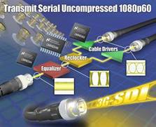
The SDI interface is a "digital component serial interface".
The serial interface is an interface that sequentially transmits each bit of data and corresponding data through a single channel. Due to the high data rate of serial digital signals, they must be processed before transmission. The early block coding is replaced by scrambling non-return-to-zero inversion (NRZI). The standards are SMPTE-259M and EBU-Tech-3267, which include digital composite and digital component signals including digital audio. Before transmission, the original data stream is scrambled and converted into NRZI code to ensure that the original data is reliably recovered at the receiving end. In this way, the digital serial interface can be understood as a kind of baseband signal modulation. The SDI interface can pass 270Mb / s serial digital component signals. For 16: 9 format images, it should be able to transmit 360Mb / s signals.
The SDI interface cannot directly transmit compressed digital signals. After the compressed signals recorded by digital video recorders, hard disks and other devices are played back, they must be decompressed and output through the SDI interface to enter the SDI system. If you repeatedly decompress and compress, it will inevitably cause image quality degradation and delay increase. For this reason, digital video recorders and non-linear editing systems of various formats have specified their own interfaces for directly transmitting compressed digital signals. (A) Sony's serial digital data interface SDDI (SerialDigital Data Interface) is used for Betacam-SX nonlinear editing or digital news transmission system. Through this interface, it can be uploaded from tape to disk at 4 times the speed. (B) Sony's 4x speed serial digital interface (QSDI) (QuarterSerial Digital Interface), in the DVCAM video recorder editing system, through this interface at 4x speed from tape to disk, from disk to tape or between disk and disk Make a copy of the data. (C) Panasonic's Compressed Serial Digital Interface (CSDI) is used in DVCPRO and Digital-S digital video recorders, non-linear editing systems, and can transfer data from the base to the base or the base at 4 times the speed .
The above three interfaces are not compatible with each other, but all are compatible with the SDI interface. In the 270Mb / s SDI system, high-speed transmission is possible. These three interfaces are designed to build digital audio and video networks. This type of network does not use the handshake protocol like computer networks, but uses synchronous network technology, and there will be no delay due to different paths.
People often embed digital audio signals in SDI signals, that is, insert digital audio signals into the video signal during line and field synchronization pulses (line and field blanking) and transmit them simultaneously with digital component video signals.
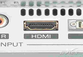
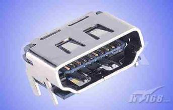
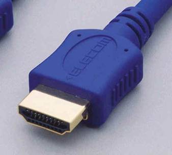
The English full name of HDMI is "High DefiniTIon MulTImedia", Chinese means high-definition multimedia interface. The HDMI interface can provide a data transmission bandwidth of up to 5Gbps, and can transmit uncompressed audio signals and high-resolution video signals. At the same time, there is no need for digital / analog or analog / digital conversion before signal transmission, which can ensure the highest quality audio and video signal transmission. The advantage of using HDMI is that only one HDMI cable is required to transmit audio and video signals at the same time, unlike the need for multiple cables to connect; at the same time, due to wireless digital / analog or analog / digital conversion, higher audio frequency And video transmission quality. For consumers, HDMI technology not only provides clear picture quality, but also simplifies the installation of home theater systems because the audio / video uses the same cable.
1.7.3 EvaluationIn April 2002, 7 companies including Hitachi, Panasonic, Philips, Silicon Image, Sony, Thomson and Toshiba established the HDMI organization and began to develop new standards dedicated to digital video / audio transmission. At the end of 2002, the HDMI 1.0 standard for High-definition Digital Multimedia Interface was released. Compared with DVI, HDMI can transmit digital audio signals, and adds support for HDCP, while providing better DDC optional functions. HDMI supports a data transmission rate of 5Gbps and can transmit 15 meters at the farthest, which is enough to cope with a 1080p video and an 8-channel audio signal. And because a 1080p video and an 8-channel audio signal require less than 4GB / s, HDMI still has a lot of leeway. This allows it to connect the DVD player, receiver and PRR separately with a cable. In addition, HDMI supports EDID and DDC2B, so devices with HDMI have the characteristics of "plug and play". The source and the display device will automatically "negotiate" to automatically select the most suitable video / audio format.
HDMI is compatible with DVI on pins, but it uses different packages:
HDMI to DVI-D adapter:
HDMI to DVI-D adapter cable:

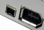

IEEE 1394, also known as FireWire or iLink, can transmit digital video and audio and machine control signals, has a high bandwidth, and is very stable. Usually it is mainly used to connect digital cameras, DVD recorders and other equipment. There are two types of IEEE 1394 interfaces: a 6-pin hexagonal interface and a 4-pin small square interface. The 6-pin hexagonal interface can supply power to the connected device, while the 4-pin quadrilateral interface cannot.
1.8.3 EvaluationIt was originally designed to be a universal connection interface between electronic devices (including camcorders, personal computers, digital televisions, audio / video receivers, DVD players, printers, etc.). The 1394 cable can transmit different types of digital signals, including video, audio, digital audio, device control commands, and computer data. The main performance characteristics of IEEE 1394 are as follows:
Digital interface: Data can be transmitted in digital form without the need for analog-to-digital conversion, thereby reducing the complexity of the device and ensuring the quality of the signal.
Hot plug: when the system is working at full speed, the IEEE 1394 device can also be inserted or removed. Users will find that adding a 1394 device is as easy as plugging the power cord into its electrical outlet.
1.9 BNC interface 1.9.1 Interface diagram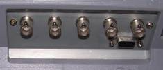

The BNC interface refers to the coaxial cable interface. The BNC interface is used for 75-ohm coaxial cable connection. It provides two channels for receiving (RX) and transmitting (TX). It is used for the connection of unbalanced signals.
1.9.3 EvaluationBNC (coaxial cable card ring interface) interface is mainly used to connect high-end home theater products and professional video equipment. The BNC cable has 5 connectors that receive red, green, blue, horizontal sync and vertical sync signals. The BNC connector can reduce the interference between the video signals and achieve the best signal response. In addition, due to the special design of the BNC interface, the connection is very tight, and there is no need to worry about loose connections and poor contact.
2 Audio interfaceIn addition to the visual impact brought by high-definition video, the audio quality has also been greatly improved, which can bring you a more realistic live effect. Make a note about the audio interface that is often mentioned at present.
2.1 RCA analog audio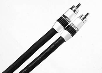
The RCA connector is commonly referred to as the lotus head, and the use of RCA cables to transmit analog signals is currently the most common audio connection method. Each RCA cable is responsible for transmitting one channel of audio signals, so for stereo signals, a pair of cables is required. For multi-channel systems, the same number of cables should be used according to the actual number of channels. For stereo RCA audio interfaces, the right channel is generally marked in red, and the left channel is marked in blue or white.
2.2 Balanced analog audio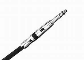
Large three-pin plug

XLR interface
It is completely different from the way that RCA analog audio cables directly transmit sound. The Balanced Analog Audio interface uses two channels to transmit signals with the same signal and opposite phases. The receiver device subtracts these two sets of signals, and the interference signals are canceled out, thereby obtaining high-quality analog signals. Balanced analog audio usually uses XLR interface and large three-core interface. XLR, commonly known as the XLR head, consists of a three-pin plug and a locking device. Thanks to the locking device, the XLR connection is quite reliable. The big three-core interface uses a plug with a diameter of 6.35 mm, which has the advantage of wear resistance and is suitable for repeated insertion and removal. Balanced analog audio connections mainly appear on advanced analog audio equipment or professional audio equipment.
2.3 S / PDIFS / PDIF (Sony / Philips Digital Interface) is a digital audio output interface jointly developed by SONY and PHILIPS. This interface is widely used in devices such as CD players, sound cards and household appliances. It can improve the sound quality of CDs and give us a more pure hearing effect. This interface transmits digital signals, so it will not be disturbed like analog signals and degrade audio quality. It should be noted that the S / PDIF interface is a standard, and both the coaxial digital interface and the optical interface belong to the category of the S / PDIF interface.
2.4 Digital coaxial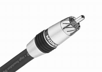
Digital coaxial (Digital Coaxial) is an interface that uses the S / PDIF interface to output digital audio. The coaxial cable has two concentric conductors, and the conductor and the shield share the same axis. The coaxial cable is a copper conductor insulated by an insulating material with an impedance of 75 ohms. Outside the inner insulating material is another layer of ring conductor and its insulator. The entire cable is sheathed with PVC or Teflon material Envelop. The advantages of coaxial cable are stable impedance and high transmission bandwidth, which ensures the quality of audio. Although the standard connector of the coaxial digital cable is a BNC connector, most of the coaxial digital cables on the market use RCA connectors.
2.5 Fiber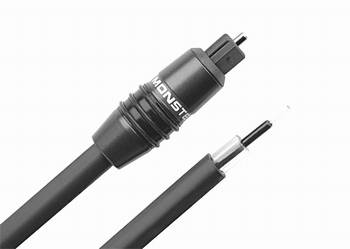
Optical fiber (Optical) transmits digital signals in the form of light pulses, and its material is mainly glass or plexiglass. The optical fiber also uses the S / PDIF interface output, which has high bandwidth and low signal attenuation. It is often used to connect DVD players and AV amplifiers, and supports PCM digital audio signals, Dolby and DTS audio signals.
2.6 Phoenix Head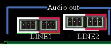
Phoenix head is also often used as an audio input and output port.
3 Video resolution 3.1 CIFCIF is a commonly used standardized image format (Common Intermediate Format). In the H.323 protocol suite, the standard capture resolution of the video capture device is specified. CIF = 352 × 288 pixels.
The CIF format has the following characteristics:
(1) The spatial resolution of the TV image is the resolution of the Video Home System (VHS), which is 352 × 288.
(2) Use non-interlaced scanning.
(3) Use NTSC frame rate, 30 frames per second.
(4) Use 1/2 PAL horizontal resolution, that is, 288 lines.
(5) Encode the luminance and two color-difference signals (Y, Cb, and Cr) components separately, and their value ranges are the same as ITU-R BT.601. That is, black = 16, white = 235, the maximum value of color difference is equal to 240, and the minimum value is equal to 16.
The following is a description of the parameters of the five CIF image formats.
sub-QCIF 128 × 96
QCIF 176 × 144
CIF 352 × 288
4CIF 704 × 576
9CIF 1056 × 864
16CIF 1408 × 1152
Currently, CIF and 4CIF are used in the video conference industry, and CIF, HALF D1 and D1 are used in the surveillance industry.
3.2 DCIFIn video surveillance, a more effective surveillance video coding resolution (DCIF) was found after research, and its pixels were 528 × 384. The DCIF resolution is the origin of the video image. The two odd and even HALF D1 are deinterlaced to form a D1 (720 * 576). D1 is processed as a boundary and becomes 4CIF (704 × 576). / 4 reduction, vertical 2/3 reduction, converted to 528 × 384. The number of pixels of 528 × 384 is exactly twice the number of CIF pixels, in order to distinguish it from the commonly said 2CIF (704 * 288), we call it DOUBLE CIF , Referred to as DCIF. Obviously, DCIF is more balanced than Half D1 in both horizontal and vertical directions.
3.3 Dx series / 720p / 1080pDx series is the standard of digital TV system display format, which is divided into the following five specifications. The 720p and 1080p of high-definition video and ultra-high-definition video that we often say are also the display formats of digital TV systems.
D1: 480i format (525i): 720 × 480 (horizontal 480 lines, interlaced scanning), the same resolution as NTSC analog TV, the line frequency is 15.25kHz, which is equivalent to what we call 4CIF (720 × 576).
D2: 480p format (525p): 720 × 480 (horizontal 480 lines, progressive scan), much clearer than D1 interlaced scan, same specifications as progressive DVD, horizontal frequency is 31.5kHz.
D3: 1080i format (1125i): 1920 × 1080 (horizontal 1080 lines, interlaced scanning), HD uses one of the most resolutions, with a resolution of 1920 × 1080i / 60HZ and a line frequency of 33.75kHz.
D4: 720p format (750p): 1280 × 720 (horizontal 720 lines, progressive scan), although the resolution is lower than D3, but because of progressive scan, more people on the market feel relative to 1080i (actually 540 lines) The visual effect is clearer. When the maximum resolution reaches 1920 × 1080, D3 feels clearer than D4, especially in terms of text expressiveness, the resolution is 1280 × 720p / 60HZ, and the line frequency is 45kHz.
D5: 1080p format (1125p): 1920 × 1080 (horizontal 1080 lines, progressive scan), currently the highest standard for civilian HD video, with a resolution of 1920 × 1080p / 60HZ and a horizontal frequency of 67.5KHZ.
Among them, the D1 and D2 standards are the highest standards of our general analog TV, and cannot be called high-definition. The 1080i standard of D3 is the basic standard of high-definition TV. It can be compatible with the 720p format, while the 1080p of D5 is only a professional standard. It is not a civilian level. The 60HZ given above is only the ideal field frequency, and its line frequency is 67.5KHZ. At present, there is no such high line frequency TV. The actual field frequency of 1080p in the professional field is only 24HZ, 25HZ and 30HZ.
It should be pointed out that the DVI interface is a special interface unique to Japan. There are few such interfaces in domestic TVs. The most is the color difference interface. The color difference interface supports up to D4. In theory, there is definitely no HDMI (pure digital signal, Support up to 1080p), the highest resolution is high, but on TVs with a resolution below 1920 × 1080, there is generally no big difference.
The video communication process is a real-time two-way complete communication process of video and audio. In this process, in order to obtain high-definition video images, we sometimes ignore another important process-the audio communication process. If we are watching high-definition video images, we cannot get a clearer, continuous audio effect. Then this process actually has no meaning, so its importance even exceeds the video. The development of audio technology is extremely slow in traditional video conference systems, because the current audio codec compression standards used in video communication are to maintain low bandwidth occupation and high codec efficiency during transmission, thereby sampling audio signals The frequency, sampling accuracy and sampling range have been greatly reduced, so that the clarity and reproducibility of the audio can be greatly reduced. Compared with the standards used for storage and playback of non-real-time compression protocols (such as OGG, MP3, etc.), the audio fidelity is very low. In this way, the restoration of live sound cannot meet the requirements to some extent. At present, G.711, G.722, G.722.1, G.728 and other audio standards are mainly used in the traditional video communication process. The audio width is only 50Hz-7KHz mono, and the natural frequency can be perceived by the human ear. The loudness can reach 20Hz-20KHz. Therefore, the loss of too much audio information during the restoration of the on-site ambient sound has caused the on-site situation to not be truly represented. Therefore, in the process of high-definition video communication, we must have an auxiliary audio processing method to solve this problem. Make the whole high-definition communication process closer to perfection.
At present, there are many international standards for audio processing technology. MPEG-1 Layer 2 or AAC series audio can be used for the next-generation real-time interactive audio processing. The principle of selecting standards is that the audio frequency response range must reach 22KHz. It can cover almost the entire range of human ear hearing, and even surpasses in high frequency. It can make the real-time audio reproduction, and can use two-channel stereo playback in the restoration, so that the sound of the entire video communication A stronger sense of proximity, reaching CD-level sound quality. At the same time, the best adaptation to link bandwidth and codec efficiency is achieved. The following is a description of various audio coding standards:
4.1 G.711 Type: Audio
Developed by: ITU-T
Required bandwidth: 64Kbps
Features: small algorithm complexity, general sound quality advantages: low algorithm complexity, small compression ratio (CD sound quality> 400kbps), the shortest codec delay (compared to other technologies)
Disadvantages: The occupied bandwidth is relatively high. Remarks: The G.711 64kb / s pulse code modulation PCM released by CCITT in the 1970s.
Developed by: ITU-T
Required bandwidth: 32Kbps
Audio bandwidth: 3.4KHZ
Features: Compared to PCMA and PCMU, the compression is relatively high, which can provide a 2: 1 compression ratio.
Advantages: Big compression ratio Disadvantages: General sound quality Remarks: Subband ADPCM (SB-ADPCM) technology. The G.721 standard is a transcoding system. It uses ADPCM conversion technology to realize the conversion between 64 kb / s A-law or μ-law PCM rate and 32 kb / s rate.
Developed by: ITU-T
Required bandwidth: 64Kbps
Audio width: 7KHZ
Features: G722 can provide high-fidelity voice quality Advantages: good sound quality Disadvantages: high bandwidth requirements Remarks: Subband ADPCM (SB-ADPCM) technology
Developed by: ITU-T
Required bandwidth: 32Kbps / 24Kbps
Audio width: 7KHZ
Features: Can achieve a lower bit rate and greater compression than the G.722 codec. The goal is to achieve G.722 roughly equivalent quality at about half the bit rate.
Advantages: good sound quality Disadvantages: high bandwidth requirements Remarks: Most of them are currently used in TV conference systems.
Developed by: ITU-T
Required bandwidth: 48Kbps / 32Kbps / 4Kbps
Audio width: 14KHZ
Features: Using the patented Siren â„¢ 14 algorithm from Polycom, it has a breakthrough advantage compared with the previous wideband audio technology, providing 14 kHz ultra-wideband audio with low latency, and the code rate is less than MPEG4 AAC-LD replacement Half of the codec, and requires only one-tenth to one-twentieth of the computing power, which leaves more processor cycles to improve video quality or run Internet applications, and mobile devices Battery life can also be extended.
Advantages: The sound quality is clearer, almost comparable to that of CD, and can reduce the fatigue of listeners in applications such as video conferencing.
Disadvantages: Polycom's patented technology.
Remarks: At present, most of them are used in video conference systems
Developed by: ITU-T
Required bandwidth: 5.3Kbps / 6.3Kbps
Audio width: 3.4KHZ
Features: Voice quality is close to good, bandwidth requirements are low, efficient implementation, easy to multi-channel expansion, can use 53540 on-chip 16kRAM C5402. It meets the voice quality required by ITU-TG723 and has stable performance. Can be used for IP phone voice source coding or efficient voice compression storage.
Advantages: low bit rate and small bandwidth requirements. And to achieve the voice quality required by ITU-TG723, stable performance.
Disadvantages: General sound quality Remarks: The G.723 speech encoder is a dual-rate encoding scheme for multimedia communications with an encoding rate of 5.3kbits / s and 6.3kbit / s. The G.723 standard is an integral part of the multimedia communication standards formulated by the International Telecommunication Union (ITU) and can be applied to systems such as IP phones. Among them, the 5.3kbits / s code rate encoder uses multi-pulse maximum likelihood quantization technology (MP-MLQ), and the 6.3kbits / s code rate encoder uses algebraic excitation linear prediction technology.
Developed by: ITU-T
Required bandwidth: 5.3Kbps (22.9)
Audio width: 3.4KHZ
Features: It can compress and decompress music and other audio signals, but it is optimal for voice signals. G.723.1 uses silent compression that performs discontinuous transmission, which means that artificial noise is added to the bitstream during silence. In addition to reserving bandwidth, this technology keeps the modem of the transmitter working continuously, and avoids the on-off of the carrier signal.
Advantages: low bit rate and small bandwidth requirements. And to achieve the voice quality required by ITU-TG723, stable performance, to avoid the carrier signal time on and off.
Disadvantages: General notes on voice quality: G.723.1 algorithm is a compression algorithm recommended by ITU-T for voice or other audio signals in low-rate multimedia services. Its target application systems include multimedia communication systems such as H.323 and H.324. At present, this algorithm has become one of the mandatory algorithms in the IP telephone system.
Developed by: ITU-T
Required bandwidth: 16Kbps / 8Kbps
Audio width: 3.4KHZ
Features: Used in multiple fields such as IP telephony, satellite communications, and voice storage. G.728 is a low-latency encoder, but it is more complicated than other encoders, because the 50-order LPC analysis must be repeated in the encoder. G.728 also uses an adaptive post filter to improve its performance.
Advantages: backward adaptation, using adaptive post filter to improve its performance Disadvantages: more complex than other encoders Remarks: G.728 16kb / s short delay codebook excited linear prediction coding (LD-CELP) In 1996, ITU announced the CS-ACELP algorithm of G.728 8kb / s, which can be used in IP telephony, satellite communications, voice storage and other fields. 16 kbps G.728 low-latency code excited linear prediction.
G.728 is a mixture of low-bit linear predictive synthesis analysis encoders (G.729 and G.723.1) and backward ADPCM encoders. G.728 is an LD-CELP encoder, which only processes 5 samples at a time. For low-rate (56 ~ 128 kbps) integrated service digital network (ISDN) video phones, G.728 is a recommended voice encoder. Due to its backward adaptive characteristics, G.728 is a low-latency encoder, but it is more complicated than other encoders, because the 50-order LPC analysis must be repeated in the encoder. G.728 also uses an adaptive post filter to improve its performance.
Developed by: ITU-T
Required bandwidth: 8Kbps
Audio width: 3.4KHZ
Features: To achieve long-distance call quality under good channel conditions, good robustness in the presence of random bit errors, frame loss, and multiple transfers. This voice compression algorithm can be applied in a wide range of fields, including IP phones, wireless communications, digital satellite systems, and digital private lines.
The G.729 algorithm uses the "Conjugate Structure Algebraic Code Excited Linear Prediction Coding Scheme" (CS-ACELP) algorithm. This algorithm combines the advantages of waveform coding and parameter coding. Based on adaptive predictive coding technology, it uses vector quantization, synthesis analysis, and sensory weighting.
The G.729 encoder is designed for low-latency applications. Its frame length is only 10ms, and the processing delay is also 10ms, plus a 5ms foresight. This makes the point-to-point delay generated by G.729 is 25ms, the bit rate is 8 kbps.
Advantages: The voice quality is good, and the application field is very wide. It uses vector quantization, synthesis analysis, and sensory weighting to provide a hidden processing mechanism for frame loss and packet loss.
Disadvantages: poor performance in handling random bit errors.
Note: The International Telecommunication Union (ITU-T) formally adopted G.729 in November 1995. ITU-T Recommendation G.729 is also called "Conjugate Structure Algebraic Codebook Excited Linear Predictive Coding Scheme" (CS-ACELP), which is a newer voice compression standard. G.729 was jointly developed by several well-known international telecommunications entities in the United States, France, Japan and Canada.
Developed by: ITU-T
Required bandwidth: 8Kbps (34.4)
Audio width: 3.4KHZ
Features: The complexity is lower than G.729, and the performance is worse than G.729.
Advantages: The voice quality is good, the calculation complexity is reduced for real-time implementation, and the hidden processing mechanism for frame loss and packet loss is provided. Disadvantages: poorer performance than G.729. Remarks: In 1996, ITU-T formulated G.729 The simplified solution G.729A mainly reduces the calculation complexity to facilitate real-time implementation, so the current use is G.729A.
Maker: MPEG
Required bandwidth: 384kbps (compress 4 times)
Audio width:
Features: Simple encoding, used for digital cassette audio tapes, 2 channels, the audio compression scheme used in VCD is MPEG-1 layer I.
Advantages: The compression method is much more complicated than the time domain compression technology. At the same time, the coding efficiency and sound quality are greatly improved, and the coding delay is increased accordingly. Can achieve "completely transparent" sound quality (EBU sound quality standard)
Disadvantages: higher bandwidth requirements Remarks: MPEG-1 sound compression coding is the first international standard for high-fidelity sound data compression, which is divided into three levels:
--Layer 1 (Layer 1): simple coding, used for digital cassette audio tapes
--Layer 2: Medium algorithm complexity, used for digital audio broadcasting (DAB) and VCD, etc.
--层3(Layer 3):编ç å¤æ‚,用于互è”网上的高质é‡å£°éŸ³çš„ä¼ è¾“ï¼Œå¦‚MP3音ä¹åŽ‹ç¼©10å€
制定者:MPEG
所需带宽:256~192kbps(压缩6~8å€ï¼‰
音频宽度:
特性:算法å¤æ‚度ä¸ç‰ï¼Œç”¨äºŽæ•°å—音频广æ’(DAB)å’ŒVCDç‰ï¼Œ2声é“,而MUSICAM由于其适当的å¤æ‚程度和优秀的声音质é‡ï¼Œåœ¨æ•°å—æ¼”æ’室ã€DABã€DVBç‰æ•°å—节目的制作ã€äº¤æ¢ã€å˜å‚¨ã€ä¼ é€ä¸å¾—到广泛应用。
优点:压缩方å¼ç›¸å¯¹æ—¶åŸŸåŽ‹ç¼©æŠ€æœ¯è€Œè¨€è¦å¤æ‚得多,åŒæ—¶ç¼–ç 效率ã€å£°éŸ³è´¨é‡ä¹Ÿå¤§å¹…æ高,编ç å»¶æ—¶ç›¸åº”å¢žåŠ ã€‚å¯ä»¥è¾¾åˆ°â€œå®Œå…¨é€æ˜Žâ€çš„声音质é‡ï¼ˆEBUéŸ³è´¨æ ‡å‡†ï¼‰
Disadvantages:
备注:åŒMPEG-1 audio layer 1
制定者:MPEG
所需带宽:128~112kbps(压缩10~12å€ï¼‰
音频宽度:
特性:编ç å¤æ‚,用于互è”网上的高质é‡å£°éŸ³çš„ä¼ è¾“ï¼Œå¦‚MP3音ä¹åŽ‹ç¼©10å€ï¼Œ2声é“。MP3是在综åˆMUSICAMå’ŒASPEC的优点的基础上æ出的混åˆåŽ‹ç¼©æŠ€æœ¯ï¼Œåœ¨å½“时的技术æ¡ä»¶ä¸‹ï¼ŒMP3çš„å¤æ‚度显得相对较高,编ç ä¸åˆ©äºŽå®žæ—¶ï¼Œä½†ç”±äºŽMP3在低ç 率æ¡ä»¶ä¸‹é«˜æ°´å‡†çš„声音质é‡ï¼Œä½¿å¾—它æˆä¸ºè½¯è§£åŽ‹åŠç½‘络广æ’çš„å® å„¿ã€‚
优点:压缩比高,适åˆç”¨äºŽäº’è”ç½‘ä¸Šçš„ä¼ æ’缺点:MP3在128KBitrateåŠä»¥ä¸‹æ—¶ï¼Œä¼šå‡ºçŽ°æ˜Žæ˜¾çš„高频丢失备注:åŒMPEG-1 audio layer 1
制定者:MPEG
所需带宽:与MPEG-1层1,层2,层3相åŒéŸ³é¢‘宽度:
特性:MPEG-2的声音压缩编ç 采用与MPEG-1声音相åŒçš„编译ç 器,层1, 层2和层3的结构也相åŒï¼Œä½†å®ƒèƒ½æ”¯æŒ5.1声é“å’Œ7.1声é“的环绕立体声。
优点:支æŒ5.1声é“å’Œ7.1声é“的环绕立体声缺点:
备注:MPEG-2的声音压缩编ç 采用与MPEG-1声音相åŒçš„编译ç 器,层1, 层2和层3的结构也相åŒï¼Œä½†å®ƒèƒ½æ”¯æŒ5.1声é“å’Œ7.1声é“的环绕立体声。
制定者:MPEG
所需带宽:48-64 kbps
音频宽度:22KHZ
特性:æ供高质é‡çš„低延时的音频编ç æ ‡å‡†ï¼Œä»¥å…¶20ms的算法延时æ供更高的比特率和å„ç§å£°éŸ³ä¿¡å·çš„高质é‡éŸ³é¢‘。
Disadvantages:
备注:超宽带编解ç 器技术支æŒé«˜è¾¾48KHzé‡‡æ ·çŽ‡çš„è¯éŸ³ä¼ è¾“ï¼Œä¸Žä¼ ç»Ÿçš„çª„å¸¦ä¸Žå®½å¸¦è¯éŸ³ç¼–解ç 器相比大幅æ高了音质。该技术å¯æ供接近CD音质的音频,数æ®é€ŸçŽ‡é«˜è¾¾48–64kbps,ä¸ä»…æ高了IPè¯éŸ³ä¸Žè§†é¢‘应用的清晰度,而且支æŒç”µè¯éŸ³ä¹ä¼ 输功能。高清è¯éŸ³é€šé“支æŒæ›´é«˜çš„é‡‡æ ·çŽ‡ï¼Œé…åˆéŸ³é¢‘编解ç 器的高ä¿çœŸéŸ³æ•ˆï¼Œæ˜¾è‘—丰富并扩展了频谱两端的音质范围,有效改善了è¯éŸ³å›žå“性能,æ高了清晰度。
Those Red Through-Hole LED was born for excellent lighting effects.
Need some really bright LEDs? Contact us now!
Red Through-hole LED is easy to use in decorated your home or garden. It's widely use in Grow Light Source, lighting, LED Lights decoration, indicator LED and other fields as well.
In 18 years, we supply the red through-hole LED with High consistency, high brightness, low light attenuation has been recognized by our customers.
1, Red through-hole LED has a lots of size like: Red Round through-hole LED, red Straw hat through-hole LED, red flat top through-hole, red Ellipse throuh-hole LED, 3mm red Through-hole LED, 5mm red Through-hole LED, 8mm red Through-hole LED, Rectangle red Through-hole LED(2*3*4 red Through-hole LED), Square red Through-hole LED and so on.
2, Variety of color available: deep red Through-hole LED, red Through-hole LED, red grow light Through-holeLED, pale red Through-hole LED. For instance: 625nm red Through-hole led, 635nm red Through-hole led, 645nm red Through-hole led, 650nm red Through-hole led, 660nm Through-hole led, ect.
3, Different brightness: common brightness red Through-hole LED, High light red Through-hole LED, Super Bright Red Through-Hole LED, Ultra bright red Through-hole LED.
4, Colorful epoxy: Water clear, red diffused, red water clear, white red diffused, white diffused.
5, Variety of angle available: 5 red degree through-hole LED, 20 red degree through-hole LED, 30 red degree through-hole LED, 40 red degree through-hole LED, 45 red degree through-hole LED, 60 red degree through-hole LED, 90 red degree through-hole LED, 120 red degree through-hole LED, 140 red degree through-hole LED ect.
6, The length of pin: LED Lamp's pin can be 17mm, 29mm, 90 degrees bent feet, braided pin and so on. Tips: taping pins can operate on a robot, greatly improving the efficiency of manual plug-ins.

We will do the High temperature resistance testing and 10 hours ageing treatment before the product out off the factory, which can ensure the stability of each product. Our LED products have 5 year warranty. Please believe that we are the best supplier for your light-emitting diode.
welcome to visit our factory.Red Through-hole LED
Red Through-Hole LED,Super Bright Red Through-Hole LED,3mm Through-Hole Red LED,5mm Red LED,8mm Red LED
Shenzhen Best LED Opto-electronic Co.,Ltd , https://www.bestsmd.com