Principle of blanking and synchronization
1. Blanking
In the TV system, the image signal is transmitted during the forward scan, and the image signal is not transmitted during the reverse trip. The retrace line appears on the fluorescent screen by the electron beam reverse scan, which will cause interference to the image of the forward path and affect the clarity of the image. Therefore, it is necessary to cut off the electron beam of the TV set during the reverse scanning of the line and field to eliminate the retrace line of the line and field, so as to realize blanking. The method is that the blanking signal is sent by the synchronous machine at the TV station to make the receiver picture tube turn off the electron beam during the line and field reverse scanning.
2. Synchronize
In the TV system, in order to make the image reproduced by the TV set exactly the same as the image taken by the camera, the electron beam scanning of the receiving end and the sending end must be synchronized. The so-called synchronization means that the frequency (fast and slow) of the scan at the receiving and sending ends is exactly the same as the phase (starting position) of the scan. If the receiving and sending end scans are not synchronized, the reproduced image is deformed or unstable. In severe cases, the image is chaotic and cannot be viewed normally.
In order to ensure the synchronization of line and field scanning at the receiving and transmitting ends, the synchronous machine of the TV station sends out line and field synchronization signals, so that the TV receiver accurately reproduces the image.
four. Camera and imaging
(1) Camera principle
The optical-electric conversion at the sending end is done by the camera tube. There are various forms of camera tubes. At present, black and white or color TV cameras widely use lead oxide (pbo) tubes with an internal photoelectric effect. Figure 07-02-10 is a schematic diagram of its structure. Its cylindrical glass casing mainly contains two parts: a photoelectric target and an electron gun. A deflection coil, a focusing coil and a correction coil are arranged outside the tube.
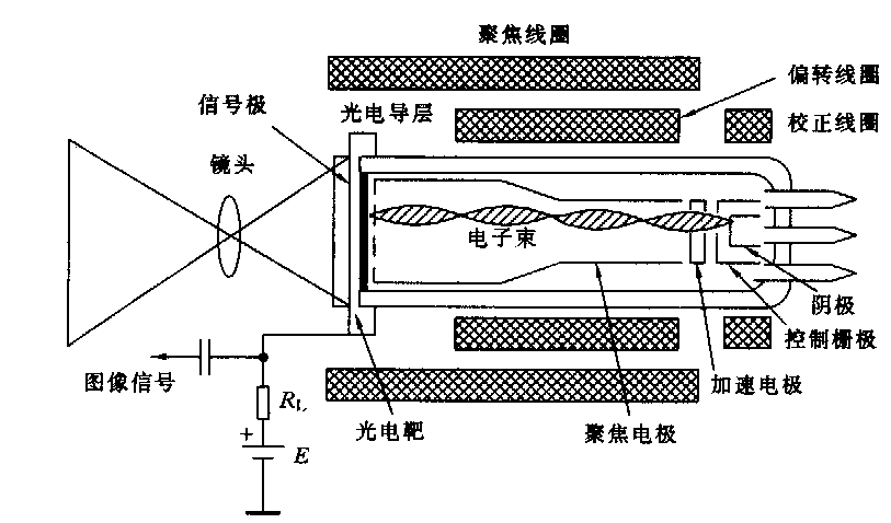
Figure 07-02-10 Camera tube
(1) Photoelectric target; a thin and transparent metal conductive film is coated on the inner wall of the glass screen in front of the camera tube as a light path and a signal output electrode. Behind the metal film is the photoelectric target. Its structure is shown in Figure 07- 02-11 (a). The photoelectric target is composed of three layers of semiconductor materials. The thicker layer in the middle is the lead oxide semiconductor (pbo), called the I layer, the layer scanned by the electron beam inside is the P-type semiconductor layer, and the layer exposed to light on the outside and in contact with the transparent metal film is the N-type semiconductor . Both the P layer and the N layer are much thinner than the I layer, so the photoelectric target of the pbo tube is actually equivalent to a photodiode, and its working performance is mainly determined by the I layer (pbo). Due to the photosensitive properties of semiconductors, when the intensity of the light shining on it changes, its equivalent resistance also changes.
(2) Electron gun: The electron gun is composed of a filament, cathode, control grid, accelerating pole, focusing pole, etc. which are covered in a vacuum glass tube. When a normal voltage is applied to each electrode, the electrons emitted by the cathode are accelerated and focused into a very thin electron beam on the photoelectric target by the acceleration electrode, focusing electrode, and high-voltage anode (mesh electrode). The electron beam is moved by the line and field deflection magnetic fields sheathed outside the tube, and moves from left to right along the target surface from top to bottom to pick up the signal.
(3) Image signal generation: The schematic diagram of the image signal generation circuit is shown in Figure 07-02-11 (b). When the image is imaged on the photoelectric target through the camera lens, corresponding to the bright spot of the image pixel, the conductivity of the photoconductive layer is high, the equivalent resistance is small, and the electron beam is scanned to Figure 07-02-10. "Bright spot", the current it forms in the loop is large, the voltage drop across the load resistance is large, and the output voltage is small. Conversely, corresponding to the dark spot of the image pixel, the corresponding equivalent resistance of the photoconductive layer is large. When the electron beam scans to the "dark spot", the current formed in the loop is small, the voltage drop across the load resistance is small, and the output The voltage is large. Obviously, the level of the image signal voltage output by the camera tube is inversely proportional to the brightness of the image, which is called a negative TV signal. By the way, if the voltage of the image signal is proportional to the brightness of the image, it is called a positive TV signal. As mentioned above, the camera tube converts the light and dark information of the pixels at each point of the image into electrical signals with voltage changes, and completes the photoelectric conversion.
|
|
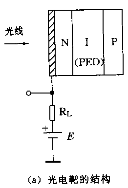
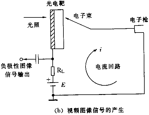
Fig. 07-02-11
Principle of three imaging
CRT is an important device to complete the electric-optical conversion at the receiving end. The schematic diagram of the picture tube is shown in Figure 07-02-12. It is composed of an electron gun and a fluorescent screen. The front end of the glass casing of the kinescope is a fluorescent screen, and the inner wall of the glass of the fluorescent screen is coated with a layer of phosphor powder, which can emit light when bombarded by an electron beam. The electron gun is composed of various metal electrodes. When an appropriate voltage is applied to each electrode, the cathode of the electron gun is baked by the filament to emit electrons, which are aggregated into a beam to bombard the fluorescent screen. The electron beam scans the fluorescent screen under the action of the magnetic field generated by the outer casing deflection coil.
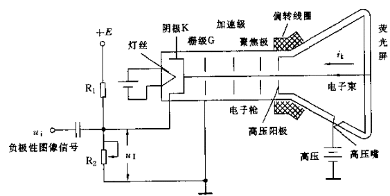
Figure 07-02-12 Schematic diagram of the picture tube
When the negative-polarity image signal is added to the cathode K, it can control the change of the grid cathode voltage, control the intensity of the electron beam current Ik, and thereby control the brightness of each point of the electron beam scanning the fluorescent screen, and restore the image on the fluorescent screen. If the image signal voltage applied to the cathode is higher, the grid cathode voltage becomes more negative, that is, the greater the negative voltage between the grid and the cathode, the weaker the electron beam current, and the darker the corresponding phosphor spot. Conversely, if the voltage of the image signal applied to the cathode is lower, the electron beam current is stronger, and the corresponding phosphor dot is brighter, which is exactly the same as the brightness and darkness of the corresponding pixel of the image at the sending end. The electron beam scans the entire fluorescent screen to form a complete image.
Fives. Gamma (g) correction
(1) The concept of gamma (g)
The photoelectric conversion characteristics of almost all CRT display devices, photographic films, and many electronic cameras in the real world are non-linear. The relationship between the output and input of these nonlinear components (for example, the relationship between the output voltage of the electronic camera and the light intensity in the scene, the relationship between the intensity of the light emitted by the CRT and the input voltage) can be expressed by a power function, its The general form is:
Output = (input) g
The g (gamma) in the formula is the exponent of the power function, which is used to measure the conversion characteristics of nonlinear components. This characteristic is called the power-law conversion characteristic. By convention, both "input" and "output" are scaled to between 0 and 1. Among them, 0 represents the black level, and 1 represents the highest level of the color component. For a particular component, one can measure the functional relationship between its input and output to find the value of g.
The actual image system is composed of multiple components, and there may be several non-linear components in these components. If all components have the conversion characteristic of a power function, then the transfer function of the entire system is a power function whose index g is equal to the product of g of all individual components. If the entire g = 1 of the image system, the output and input have a linear relationship. This means that the ratio of the intensity of any two image areas in the reproduced image is the same as the intensity of the two areas of the original scene, which seems to be the goal pursued by the image system: to reproduce the original scene truly. But the actual situation is not exactly like this.
When this regenerated image is viewed in a "bright environment", that is, an environment where the brightness of other white objects is almost the same as the brightness of the white part of the image, the system of g = 1 can indeed make the image look like the "original scene" "same. However, some images sometimes get better results when viewed in a "dark environment", which is the case for film projection and slide projection. In this case, the value of g is not equal to 1, and it is generally considered that g »1.5, the scene seen by the human perspective system seems to be the" original scene ". From this point of view, the g value of the projected slide is designed to be around 1.5 instead of 1.
There is also an environment called the "dim environment" of the intermediate environment, which is like other things in the room can be seen, but the brightness is darker than the white part of the image. This is the case for watching TV and computer room. In this case, it is generally considered that the reproduced image needs g »1.25 to look like an" original scene ".
(Two) g correction
All CRT display devices have power-law conversion characteristics, if the manufacturer does not specify, then its g value is approximately equal to 2.5. The user may be powerless to change the characteristics of the glowing phosphorescent material, so it is difficult to change its g value. In order to make the g value of the whole system close to the g value required for use, at least a nonlinear component that can provide g correction is needed to compensate the nonlinear characteristics of the CRT.
In all broadcast and television systems, g correction is done in the camera. The original NTSC television standard required the camera to have a power function of g = 1 / 2.2 = 0.45, and now the power function of g = 0.5 is adopted. The PAL and SECAM TV standards specify that the camera needs to have a power function of g = 1 / 2.80 = 0.36, but this value is already too small, so the actual camera is likely to be set to g = 0.45 or 0.5. The image obtained using this camera is corrected in advance. When the image is displayed on the CRT screen with g = 2.5, the screen image relative to the original scene g is approximately equal to 1.25. This value is suitable for viewing in "dark environment".
The past era was the "analog era", but now it has entered the "digital era", and the TV image entering the computer still has the correction of g = 0.5. Don't forget this. Although TVs with g-values ​​work very well in the digital age, especially images created in specific environments work in the same environment. However, when working in other environments, the displayed image often makes people look too bright or too dark, so g correction should be done under possible conditions.
Where to do g correction is a matter of concern to people. From acquiring an image, storing it as an image file, and reading out the image file until displaying the image on a certain type of display screen, at least 5 of these links can have non-linear conversion functions and can introduce g values. E.g:
| camera_gamma: g of the image sensor in the camera (usually g = 0.4 or 0.5) |
| encoding_gamma: The encoder introduces g when encoding image files |
| decoding_gamma: Introduce g when the decoder reads the image file |
| LUT_gamma: Introducing g in the image frame buffer lookup table |
| CRT_gamma: g of CRT (usually g = 2.5) |
In the digital image display system, since the image to be displayed is not necessarily the image from the camera, it is assumed that the g value of this image is equal to 1. If encoding_gamma = 0.5, CRT_gamma = 2.5 and decoding_gamma, and LUT_gamma are all 1.0, g is approximately equal to 1.25.
According to the above analysis, in order to view the "original scene" in different environments, g correction can be added at an appropriate place.
Medical Actuator
Medical series mainly apply for medical equipment, such as hospital bed, dental chair, rehabilitation training equipment, etc. They are very quiet so that you can barely notice it. More than 4 models are available for different requirements. Max. load ranges from 6,000N to 12,000N. There are different controllers to be chosen, including handset and control box.

Medical Care Actuator,Electric Linear Actuator,Actuator For Patient Lift,Dc Medical Care Actuator
TOMUU (DONGGUAN) ACTUATOR TECHNOLOGY CO., LTD. , http://www.tomuu.com