ISP algorithm based on variable length exchange
The traditional crossbar uses a simple first-in-first-out (FIFO) input queue technology, which inevitably produces head of line (HOL) phenomenon. HOL greatly reduces the throughput of the crossbar. For example, when the packet arrives in a Bernoulli process that is subject to independent and identical distribution, and N approaches infinity, the throughput of the crossbar is only 58.6%. For burst packet arrival, the utilization rate is lower [2].
Different from the traditional ISP algorithm, the ISP algorithm proposed in the design scheme of this paper is oriented to variable length exchange. The specific process of the algorithm is as follows:
1) Initialization: Set RRi to all 0s and S to all 1, where RRi represents the VOQ with the highest priority in the i-th input port; S represents the output port state vector, and 0 means that output port i has been assigned to an input port , 1 means the port has not been assigned yet.
2) Ar [k, i] represents the i-th arbitration in the k-th scheduling, in which one scheduling iteration is N times, each iteration is called an arbitration, and one arbitration only selects the output port for one input port. Each time Ar [k, i] includes the following steps:
(1) Polling input port Pin [i] = (k + i) mod N;
(2) Determine S∩reqi (request vector of the i-th input port), if it is an empty set, add 1 to i, and return to (1) for the next iteration, otherwise go to step (3);
(3) According to RRi, reqi and S, select the output port Pout [j] for the current input port Pin [i], and output the In ∕ Out port set Ω = {<i, j>, 0
System circuit design
The OBS receiving and scheduling module mainly completes the following functions:
1) Receive burst packets from OBS core nodes, and disassemble each burst packet into one or more IP packets;
2) Exchange the disassembled IP packets and assign them to different ports according to their destination addresses;
3) Encapsulate the exchanged IP packets into Ethernet frames and transfer them to the user end (Ethernet card interface).
The Field Programmable Gate Array (FPGA) used in this article is embedded in the Field Programmable System Chips (FPSC). Since each FPSC only provides 4 data channels, 6 independent data must be processed by two FPGAs. And because the logic function completed by each FPGA in the design scheme adopted in this article is completely consistent, only a block diagram of the FPGA system implementation is given.
As shown in Figure 1, each FPGA processes 4 channels of data, 3 of which are burst packet data, and the other channel of data is an IP packet from another FPGA. Therefore, the two FPGAs can communicate with each other and work together to process six bursts of packet data. The following describes the implementation of each submodule.

Fig.1 Hardware block diagram of OBS receiving scheduling system
2.1 Clock extraction and serial-parallel conversion module
The data flow in the OBS network is bursty, rather than continuous transmission. This burstiness requires that the receiving end must quickly recover the clock signal from the input data stream. Specifically, the lock time of the phase-locked loop that requires clock extraction in the design scheme of this paper is kept in the order of nanoseconds. Therefore, in order to ensure the high efficiency of burst reception, before the burst packet enters the subsequent operation, a high-speed phase-locked loop must be passed to obtain the clock signal at the sending end, so as to achieve synchronization of sending and receiving. In addition, current FPGAs cannot handle 1.25 Gb / s serial high-speed signals, so high-speed serial signals must be converted into low-speed parallel signals through serial-to-parallel conversion to achieve internal FPGA operations. The function of the clock extraction and serial-parallel conversion module is to recover the originating clock with a frequency of 1 250 MHz from the OBS data stream, and then perform 1:40 serial-parallel conversion to generate a 40 b low-speed data stream and send it to the alignment module.
3.2 Burst Packet Alignment Module In view of the randomness of the burst packets arriving at the receiving port, burst packets must be aligned before entering the unpacking module, otherwise it will greatly increase the complexity of subsequent design and reduce the operating frequency. The burst packet alignment module is actually a sequence detector. Once the preamble is detected (see Figure 2 burst packet format), it is placed on the highest 8 b of the 40 b data unit, which is the aligned burst packet. .

3.3 Unpacking and encapsulation module The unpacking module determines whether the burst packet arrives at the receiving module by judging the preamble (marker of the start position of the burst packet). If burst data arrives, the number and length information of IP packets are extracted from the packet, and then the burst packet is decomposed into original IP packets without labels. Since the data exchange width inside the chip is 32 b, these packet data should be filled into IP packets with a length multiple of 32 b to complete the subsequent processing. In addition, the unpacking module will send a signal start_end to mark the start and end of the IP packet to avoid the exchange and encapsulation module counting the modulo of the data packet, thereby simplifying the logic and increasing the operating frequency. This is a feature of the design scheme of this article.
Figure 3 Block diagram of scheduler hardware implementation Input port polling RR pointer generator Current request generator micro arbiter (ma) output port 0 state controller output port 3 state controller output port 1 state controller output port 2 state controller current_portreq0req1req2req3rrcrrdengnts1s3s2s0S & matched_portfree 1free 3free 0free 2start_end0start_end1start_end2start_end3current_port
The encapsulation module encapsulates the IP packet into an Ethernet frame according to the format of the Ethernet frame. Since the Ethernet frame header is 22 bytes, which is only 16 b instead of an integral multiple of the chip's internal data exchange width of 32 b, there is a high 16-bit Ethernet frame header, and a low 16 b is an IP packet data unit, so use A FIFO with a width of 32 b cannot correctly generate this data unit. This design scheme divides the scheduled 32 b data into high 16 bits and low 16 bits, and stores them in two FIFOs with a width of 16 bits respectively. This data unit is generated by controlling the read signals of the two FIFOs, thus This problem is solved.
3.4 VOQ and crossbar
VOQ is used to store IP packets of different output ports, so the length of VOQ is directly related to the packet loss rate (the longer the length, the smaller the packet loss rate). Because the minimum length of a burst packet is 12.5 kbytes, each input port corresponds to 3 or 4 VOQs, and every 3 or 4 VOQs compete for an output port, then when the bandwidth utilization rate is 90%, the average The minimum length of each VOQ is 8.44 kbytes. The crossbar consists of 4 multiplexers (MulTIplexer, MUX) with enable. There are three 4 × 1 multiplexers and one 3 × 1 multiplexer.
3.5 ISP scheduler based on variable-length switching Figure 3 is an implementation block diagram of the variable-length switching ISP scheduler. It mainly consists of input port polling, RR pointer generator, current request generator, micro-arbiter and output port state controller. The specific implementation process is as follows.
3.5.1 Input Port Polling The input port polling module is equivalent to a timing generator, which generates the input port polled by this arbitration. It consists of two modulo-4 counters cnt1 and cnt2. cnt2 represents the number of iterations in each scheduling, plus 1 every 4 clock cycles. cnt1 indicates the port that should be polled first in the current iteration. When cnt2 is equal to 3, cnt1 is increased by 1. cnt1 + cnt2 indicates the port number that should be polled for the current iteration.
3.5.2 RR pointer generator
The RR pointer generator is composed of 4 two-bit RR pointer registers and a 4 × 1 multiplexer. 4 × 1MUX selects the corresponding RR pointer according to the current iteration port number and sends it to the micro-arbiter. When the number of iterations is 0, the RR pointer generator modifies the corresponding RR pointer according to the input / output matching result and according to the ISP algorithm.
3.5.3 Current request generator The current request generator generates the request signal (cr) for the arbitration based on the request signal (re), the current polling port signal (rr) and the output port status information (s) from the VOQ . At the same time, through the arbitration signal (gnt) sent by the micro arbiter and the release signal (free) given by the output port state controller, modify the In / Out port state and matching signal (s & matched port), and control the corresponding VOQ reading Enable signal (rden). The condition that the signal (cr) is valid is that both req and s are valid. The condition that s is valid (the output port is idle) is that free is valid and gnt is invalid. While the output port is busy when gnt is valid, s is invalid.
3.5.4 Micro-arbiter The micro-arbiter mainly implements the function ma according to the rr and cr signals, thereby generating gnt. The design scheme used in this paper uses an encoder called thermometer encoding [3]. This encoder performs special encoding on the highest priority and uses this to pre-process the input request, thereby cleverly eliminating the programmable priority encoder. Priority programmability, and simple hardware implementation, saving resources.
3.5.5 Output port state controller As mentioned earlier, the design scheme in this article uses a method similar to frame delimitation, which uses a signal called start_end sent by the unpacking module to mark the start and end of IP packets . When start_end is "10", the state controller starts to work; when start_end is "01", it indicates that the IP packet transmission is completed, and at this time, a free signal is sent to release the corresponding output port. This approach actually replaces the role of the modulo counter, while simplifying the logic and increasing the operating frequency.
3.5.6 Performance analysis and simulation results Literature [2] pointed out that for the keep full arrival process, the ISP algorithm's switching bandwidth utilization rate is 100%; under the conditions of independent identical distribution or burst arrival, the delay of the ISP algorithm and the cell delay The mean square error is smaller than other algorithms. This shows that ISP is excellent in bandwidth utilization, delay and fairness, especially under light load and small number of ports, ISP performance is optimal. Figure 4 is the simulation waveform diagram of the layout of the scheduler module in the design of this article after wiring.
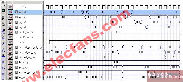
Figure 4 Timing diagram of the scheduler after placement and routing
Hardware implementation of OBS edge node receiving scheduling module
A high-quality desk lamp can help you brighten up your home office or work area so that you can finish your work and not miss a single detail. Desk lamps are also the perfect solution if you are a student and need help finishing your homework at night. Finding a light that doesn`t hurt your eyes, but illuminates your work space is important when shopping for a new desk lamp. Desk lamps also come in many shapes and sizes, so make sure you look at the dimensions of a desk lamp before purchasing based on the area you have to complete your work.
500-800 Lumen LED Desk Lamp
Shenzhen Superlight Technology Co., Ltd. , https://www.superlighttech.com