There are numerous resources available to introduce TVS diodes, many of which are in Chinese and often translated. At the end of this article, you'll find a list of all the downloadable files. Here, we focus on explaining the principle, characteristics, and key parameters of TVS diodes. We also discuss how to select the right one for thermal management and provide some insights into PCB layout considerations.
A Transient Voltage Suppressor (TVS) is a high-performance protection device that functions similarly to a Zener diode but with enhanced performance. When subjected to a reverse transient surge, the TVS rapidly switches from a high-impedance state to a low-impedance state, effectively clamping the voltage across its terminals to a safe level. This allows it to absorb and dissipate large amounts of energy from surges on power or signal lines.
Unidirectional TVS diodes behave like Zener diodes, conducting only in the forward direction and typically used in DC circuits where only positive surges are expected. On the other hand, bidirectional TVS diodes can handle surges in both positive and negative directions, making them suitable for both AC and DC applications.
Below is a visual comparison to help clarify the differences between unidirectional and bidirectional TVS diodes:
[Image: Introduce the principle, characteristics, and parameters of TVS tube]
TVS diodes have several advantages, including fast response time, high transient power handling capability, low leakage current, controllable clamping voltage, compact size, and no damage limit. However, they do come with some drawbacks, such as lower breakdown voltage and higher cost compared to other devices like MOVs.
When comparing TVS with MOVs, it's important to consider factors like response time, clamping voltage, and energy absorption capacity.
Now, let's look at the key parameters of TVS diodes:
1. **Breakdown Voltage (V(BR))** – The voltage measured across the TVS when a specific test current (I(BR)) is applied during breakdown.
2. **Maximum Reverse Pulse Peak Current (IPP)** – The maximum peak current the TVS can handle during a surge, under specified pulse conditions.
3. **Maximum Reverse Working Voltage (VRWM)** – The voltage across the TVS under normal operating conditions, typically 0.8–0.9 times the breakdown voltage.
4. **Maximum Clamp Voltage (VC(max))** – The highest voltage the TVS will allow across its terminals during a surge. It should be lower than the maximum safe voltage of the protected device.
5. **Reverse Pulse Peak Power (PPR)** – Calculated as PPR = IPP × VC(max), and it depends on the pulse waveform, duration, and temperature.
6. **Capacitance (CPP)** – Determined by the silicon chip size and bias voltage. Higher capacitance may affect the TVS's response time.
7. **Leakage Current (IR)** – The small current that flows through the TVS when the VRWM is applied, which can impact quiescent current in sensitive applications.
Understanding these parameters is crucial for selecting the appropriate TVS for your circuit. Additionally, the rated energy of the TVS must be considered, especially if repeated surges are expected. Even if each individual pulse is small, the cumulative effect can exceed the TVS's rating over time.
In practical design, it's essential to ensure that the TVS can handle the expected surge energy and that the circuit layout supports effective heat dissipation. Proper selection and placement of TVS diodes can significantly enhance the reliability and longevity of electronic systems.
Wirless Battery Par Lights
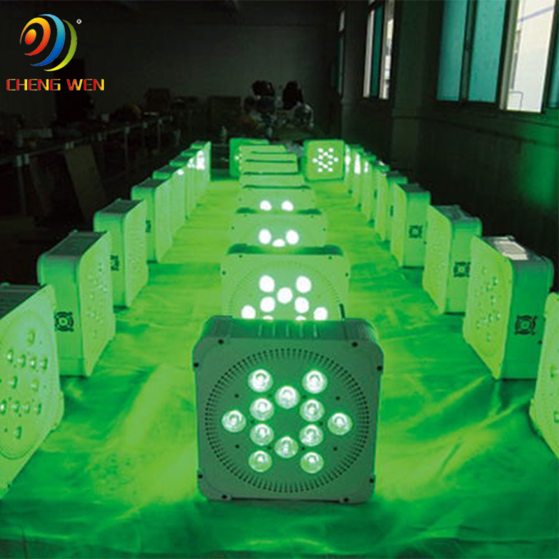
This series is LED wireless battery par light, the wireless design makes it more portable, the chassis design is compact, the weight is moderate, and it is convenient to transfer in the place. In addition to the traditional DMX signal control, the convenient mobile app control has become a more convenient control method, and the color and brightness are not inferior to conventional par lights. Equipped with a flight case with a socket, it is convenient to charge the lamp anytime and anywhere, and it can be taken out for use when it arrives at the destination, and it can be used for 24 hours after being fully charged.

Wireless Battery Par Lights ,Wireless Battery Par Lights,Wireless Led Par,Wireless Led Par Lights
Guangzhou Cheng Wen Photoelectric Technology Co., Ltd. , https://www.cwdisplay.com
