The multi-lamp driving scheme only needs to add some supporting circuits, and each channel in the DS3984 and DS3988 can drive more than one CCFL. Figure 1 shows the application circuit for driving four lamps per channel. With only a slight adjustment, you can also drive two, three, four, or more lights per channel.
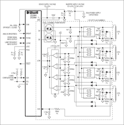
Click for larger image Figure 1. Application example of driving four lamps per channel
From Figure 2 we can also see a disadvantage when using a single channel to drive multiple lamps. Since the feedback signal amplitude of lamp B is higher than that of other lamps, the duty ratio of the power MOSFET shared by multiple lamps will be controlled by it, so that lamp B controls the power supplied to other lamps. As shown in Figure 2, this makes the current drawn by the other lamps smaller than its target value of 5mARMS.
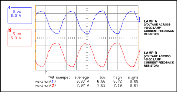
Figure 2. Voltage across the lamp current detection resistor (only two lamps are shown)
Figure 3 shows the situation when the lamp current detection signal is converted to the LCM input of the DS3984 and DS3988. Unlike the scheme for driving a single lamp per channel, AC coupling capacitors are not used for the LCM input in a multi-lamp application per channel. The DS3984 / DS3988 controller controls the lamp current based on the peak signal measured at the LCM input. Without AC coupling capacitors, the peak control level is the DC common voltage (1.35V) plus the lamp regulation threshold (1.0V), or 2.35V (average). Therefore, the peak value of the current detection signal generated by the detection resistor must be attenuated to the target value of 2.35VPEAK and then sent to the LCM, so that the device can control the lamp current at an appropriate level. Example: In Figure 1, 1000 The 7.07VPEAK signal is generated on the detection resistor, and it must be attenuated to 2.35VPEAK before reaching the LCM input.
When the signal passes through the small signal diode, the amplitude will be attenuated by about 500mV. The rest is attenuated by a resistor divider. In the example shown in Figure 1, the resistor divider consists of 8.2k And 5.1k
Resistance composition. The 50k input impedance inside the LCM pin will cause slight attenuation. Internal 50k
Impedance makes 5.1k
The voltage divider resistance drops to 4630
; Increase the attenuation.
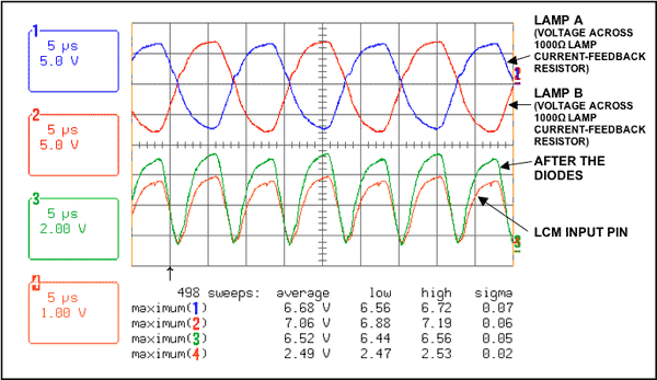
Figure 3. Lamp current feedback signal path
Figure 4 shows the overvoltage feedback signal input to the OVD terminal of the DS3984 or DS3988. When the signal passes through the small signal diode, the amplitude is reduced by about 500mV. A resistor divider is used to further attenuate it. In the circuit of Figure 1, the resistor divider consists of 33k And 5.1k
Resistance composition. OVD pin 50k
The input impedance of will increase the attenuation slightly. This 50k
The input impedance makes 5.1k
The voltage divider resistance drops to 4630
, Thus increasing the amount of attenuation.
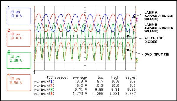
Figure 4. The output voltage of the capacitive voltage divider and the OVD signal path
In order to ensure that all lamps are properly lit and detect whether any lamps are extinguished during normal operation, some additional circuits must be used to pull down the LCM input when there are any unlit lamps. Four comparators LM339 can be used to achieve this purpose. Each comparator corresponds to a lamp. If all four lamps are lit, the forward voltage swing on the lamp current detection resistor will turn the peak detector (by the diode, 470pF capacitor and 330k Resistor composition) Charge to a reference voltage higher than 5V. At the same time, the open collector outputs of the four comparators (they are wired or connected) are turned off, allowing the lamp current signal to enter the LCM pin. If one or more lamps are not lit, the corresponding comparator pulls the LCM pin low, telling the DS3984 / DS3988 that there are still unlit lamps.
Figure 5 shows the peak detection signal that appears at the input of the comparator. Figures 6, 7, and 8 show the normal and abnormal start-up conditions and the conditions when a lamp is open.
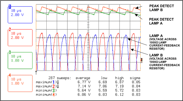
Figure 5. Peak detection signal
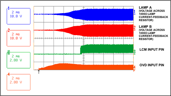
Figure 6. Normal start
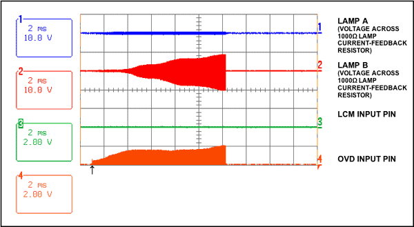
Figure 7. Start-up situation when lamp A is off
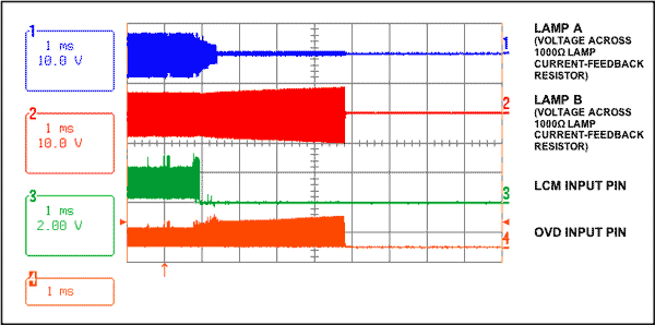
Figure 8. The situation when lamp A is off during normal operation
Yellow Box Candle export to Ghana market. 38G Yellow Box Candle is the most popular in Ghana. It is Bright Candle . The feature of Yellow Glass Jar Candle is White, Stick, wax Candle. The package of Yellow Scented Candle With Box is 8pcs/box 30boxes/ctn . Yellow Glass Jar Candle's sample are free, you just pay expree fee. The good quality and best price of Yellow Box Candle will be satisfited with you. About brand,we can do your own brand.
Welcome to order.
Yellow Box Candle
Yellow Box Candle,Yellow Glass Jar Candle,Yellow Scented Candle With Box,38G Yellow Box Candle
Shijiazhuang Zhongya Candle Co,. Ltd. , https://www.zycandlefactory.com