The principle and realization of MPEG-4 encoding in PC
The contradiction between the increasing volume of multimedia communication and the limited communication bandwidth is becoming increasingly prominent. In order to reduce the amount of data transmitted, the International Telecommunication Union and MPEG standards organizations have developed their own video compression standards. Among them, the latest MPEG-4 standard is widely used in fax, video on demand, video conference, medical image transmission and other fields due to its high compression rate, support for low bit rate transmission and object-based encoding.
MPEG-4 inherits the concepts of MPEG-2 grades and grades. There are four types of video grades, audio grades, graphic grades and scene description grades. The grade is an encoding tool adopted for a specific application. It is a subset of the tool set provided by MPEG-4, and different grades are different subsets. Each grade is divided into one or more levels, and the level defines the specifications of the bitstream parameters, in fact, it limits the performance that should be provided for decoding an encoding sequence.
The unique feature of MPEG-4 is that it supports content-based encoding and decoding. For this reason, the concept of audiovisual object AVO (Audio / Video Object) is introduced. AVO can be a violin or piano sound in an image. Each AVO can be encoded independently, but there is a spatial-temporal structure relationship between each other. Therefore, when encoding, the composition structure of the encoded object must be transmitted. To represent the spatiotemporal structure relationship between AVOs in the scene. According to this "scene description", the relevant contents of the image and sound are edited and operated during decoding. The audiovisual object can also be a rectangular frame, thus making MPEG-4 compatible with the original MPEG standard. The video object VO in the audiovisual object is usually described by three types of information, namely motion, shape and texture information.
1 Coding principle
The MPEG-4 encoder is mainly composed of three parts: shape coding, texture coding and motion coding. The frame format is divided into I-VoP, P-VOP and B-VOP. Only I-VOP and P-VOP are discussed here. I-VOP uses texture coding to eliminate the spatial redundancy between image data in one frame; P-VOP refers to the previous frame image and uses two parameters to encode. One is the difference between the current image to be encoded and the reference image; the other is the motion vector. The specific structural module of the encoder is shown in Figure 1. 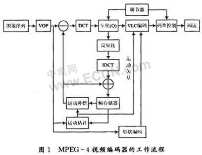
1.1 Shape coding
Shape coding is mainly used to record the shape information of the VOP extracted from the image sequence, which is divided into binary shape information and gray-scale shape information. Binary shape information uses two values ​​of 0 and 1 to represent the shape of the VOP; gray-scale shape information uses 0 to 255 to represent the different transparency of the VOP area. When encoding, when the extracted VOP has a non-rectangular shape, it is necessary to extend the boundary to make the rectangular boundary be a multiple of 16, while ensuring the smallest area after expansion, and then shape encoding; when the extracted VOP is rectangular When (the length and width of the rectangle are multiples of 16), the shape coding will be masked.
1.2 Texture encoding
Texture coding mainly encodes image pixels in I-VOP or difference pixels in P-VOP, including DCT, quantization, DC and AC prediction, entropy coding and other processes to maximize the removal of the pixels between the current VOP Spatial redundancy.
The first frame of the video is coded in I-VOP format, and the remaining frames are in I-VOP or P-VOP format, which is constrained by two factors. The user will set the format of the current frame according to the IPPPIPPPI method; the second is that the current frame has been artificially set to P-VOP, and the value of mad_P is calculated through motion estimation. If mad_P meets one of the following two conditions, the current frame P-VOP encoding format is used, otherwise I-VOP encoding format is used.
Condition 1: mad P <50/3;
Condition 2: mad P <50, and IntraMBRaTIo <0.4. Among them, IntraMBRaTIo is the proportion of macroblocks using the MBM_INTRA prediction mode in the total macroblocks in the current frame.
The DCT and quantization modules in texture coding are relatively simple. I will skip them here and focus on the remaining texture coding modules.
1.2.1 DC and AC prediction
After the DCT and quantization of the 8 × 8 block, the coefficient arrangement shows the following rule, that is, non-zero coefficients are concentrated in the upper left corner, and most of the 0 coefficients are concentrated in positions that deviate from the DC coefficient to the right and down. In particular, the DC coefficients, AC coefficients in the first row and the first column have non-zero and large values. If they can be replaced with smaller values, the number of encoded bit streams will be reduced, so DC and AC predictions are generated.
In MPEG-4, a macroblock is usually divided into 6 8 × 8 blocks for DC and AC prediction.
First, DC prediction is performed on 8 × 8 blocks. As shown in FIG. 2, X represents the current 8 × 8 block; A, B, and C represent the adjacent 8 × 8 blocks of X, and their positions are located on the left, upper left, and upper sides of X, respectively. The DC prediction of X is to predict the DC coefficient value of X by using the DC coefficient value of the adjacent block. The key is to select the DC coefficient of which adjacent block. 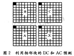
The program uses the following strategy to select adjacent blocks. Define the DC coefficient values ​​of blocks A, B, C, and X as DC_A, DC_B, DC_C, and DC_X, respectively.
If the difference between DC_A and DC_B is smaller than the difference between DC_B and DC_C, then DC_A and DC_B are relatively close in value, that is, the value in the vertical direction is closer than in the horizontal direction, so DC_C is used to predict DC_X; The values ​​are relatively close, that is, DC_A is used to predict DC_X.
The DC coefficient of the current block and the DC coefficient of the neighboring block used for prediction are subjected to a specific process to make a difference, and the difference is stored in the DC position of the current block, and the prediction direction of the DC coefficient is recorded at the same time.
AC prediction is mainly for the first row or first column AC coefficients of the 8 × 8 block, and its prediction direction depends on the prediction direction of the DC coefficient of the current block. As shown in Fig. 2, if the previous DC prediction is horizontal prediction, the AC coefficients of the first column of the current block X are predicted using the AC coefficients of the first column of the A block, and the 7 AC coefficients of the first column of X are taken as absolute values. It is added to the variable S1 (the initial value of S1 is 0). The AC coefficients of the first column of the current block are different from the AC coefficients of the first column of the adjacent block A used for prediction, and the 7 difference values ​​are stored in the position of the AC coefficients of the first column of the current block, and 7 differences The values ​​are taken as absolute values ​​and added to the variable S2 (the initial value of S2 is 0). If the previous DC prediction is vertical prediction, only the AC coefficient prediction of the first row of the current block X is performed, and the prediction step is the same as the AC coefficient prediction of the first column.
Sometimes AC prediction will produce a large prediction error, and does not achieve the purpose of saving bitstream, so it is necessary to judge the validity of AC prediction. In the AC prediction of a single 8 × 8 small block, the sum of the absolute values ​​of the AC coefficients of the first row or first column of this small block is recorded with S1, and the 7 predictions of the first row or first column after S2 are recorded. The absolute sum of the differences. Taking six 8 × 8 small blocks of one macro block as a unit, the difference between S1 and S2 of each small block is added to obtain the value S. If S is non-zero, then this macroblock performs AC prediction, its flag ACpred_flag is set to 1, otherwise this macroblock does not perform AC prediction, and ACpred_flag is set to 0.
1.2.2 Zigzag scanning
After DC and AC prediction, zigzag scanning is performed on the coefficients of 8 × 8 blocks. There are three scanning modes: Zigzag, Zigzag_v (alternating vertical scanning) and Zigzag_h (alternating horizontal scanning). Which scanning method is used is determined by three factors, namely, intra-frame or inter-frame prediction, the value of the AC prediction flag ACpred_flag, and the prediction direction of the DC coefficient.
For intra-predicted macroblocks, if the AC prediction flag ACpredflag is 0, then all 6 8 × 8 blocks in this macroblock are scanned using Zigzag; if the AC prediction flag is 1, then 6 8 × s in this macroblock The 8 blocks will determine the scanning direction of the AC coefficients according to their respective DC prediction directions. If the DC prediction is horizontal prediction, the 8 × 8 block uses the Zigzag_v scanning method to scan the coefficients, otherwise the Zigzag_h scanning method is used.
For the inter-predicted macroblocks, each 8 × 8 block uses the Zigzag scanning method to scan the coefficients.
After the zigzag scan of the 8 × 8 coefficient matrix, most of the non-zero coefficients are concentrated in the front of a one-dimensional array, and most of the zero coefficients are concentrated in the back of the one-dimensional array. Based on this feature, run length coding is generated.
1.2.3 Runlength encoding and entropy encoding
The so-called run-length coding is to perform specific processing on the AC coefficients of the 8 × 8 coefficient matrix to make it into a three-dimensional vector (Last, Run, Level) with a smaller number. Among them, Level represents the size of non-zero coefficient. Run represents the number of consecutive 0s in front of Level. Last represents the termination flag: when the value is 0, it means that there is a coefficient other than 0 after Level; when the value is 1, it means that the coefficient is the last number that is not 0; the remaining coefficients are all 0. Run-length coding generates a three-dimensional vector, compresses the amount of data, and then uses the different combinations of Last, Run, and Level as indexes to find the codewords in the corresponding Huffman coding table to generate a code stream.
1.3 Motion coding
Motion coding performs motion estimation and compensation on the current P-VOP and reference VOP to reduce the time correlation between frames and achieve compression.
Usually block matching method is used for motion estimation. The block matching method is to find the minimum matching block of the absolute error and (Sum of AbsoluteDifference, SAD) of the image block from a certain area of ​​the reference frame for an image block of a certain size in the current frame, and use this matching block to predict the current Piece. The absolute error sum of an image block refers to the sum of absolute values ​​of pixel differences in two image blocks of the same size. The SAD16 × 16 function implements the absolute error sum between the current macroblock and the reference macroblock; the SAD8 × 8 function implements the absolute error sum between the current 8 × 8 block and the reference 8 × 8 block.
After the block matching criterion is determined, the search for the optimal matching point is to be performed. The MPEG-4 verification model finally uses the Diamond Search (Diamond Search, DS). The diamond search method is a fast search method that uses the shape and size of the search template to have an important impact on the speed and accuracy of the motion estimation algorithm. Two search templates with different shapes and sizes are selected: one is the Large Diamond Search Pattern (LDSP), which has 9 candidate positions: (0, 0), (0, 2), (1 , 1), (2,0), (1, -1), (0, -2), (-1, -1), (-2,0) and (-1,1). The specific template is shown in Figure 3. One is the Small Diamond Search Pattern (SDSP), which contains 5 candidate positions: (0, 0), (0, 1), (1, 0), (0, -1) and (- 1, 0). The specific template is shown in Figure 4. 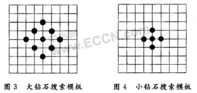
The diamond search process is as follows: the starting point coordinates of the upper left corner of the current macroblock of the current frame are used as the origin of the large template (0, 0), and within the search range of the reference frame, the (0, 0), (0, 2), (1,1), (2,0), (1, -1), (0, -2), (-1, -1), (-2,0) and (-1,1) The pixel point is used as the starting point of the upper left corner of the macro block. The macro block and the macro block of the current frame are subjected to SAD16 × 16 operation. The starting point of the upper left corner with the smallest SAD16 × 16 value is selected as the temporary best matching point. The displacement between the starting points in the upper left corner is the motion vector. Determine whether this motion vector is suitable for a specific rule. If it is not suitable, then conduct a new round of large diamond template search until a motion vector suitable for the condition is found. Then take the best matching point searched by the large diamond template as the center point (0, 0), and use the small diamond search template to perform (0, 1), (1, 0), (0, -1) and (-1, 0) Accurate search of four reference points, the smallest point of the SAD16 × 16 value found is the final best matching point, and the displacement between the best matching point and the starting point of the upper left corner of the current macroblock is the final motion vector.
The above is a full pixel search based on macroblocks, and you can also choose whether to perform a full pixel search based on 8 × 8 blocks. Use the macroblock-based motion vectors that have been obtained to find the best matching point based on the macroblock. This matching point is the center (0, 0), and the other matching points are (-1, -1), (0, -1), (1, -1), (-1, 0), (1, 0), (-1, 1), (0, 1), (1, 1), using these 9 matching points as the starting point of the upper left corner of the 8 × 8 pixel block, the 8 × 8 block and the current frame ’s 8 × 8 The block performs the sum of absolute differences and selects the starting point of the upper left corner with the smallest SAD8 × 8 value as the best matching point to find the best motion vector to obtain the motion vector and SAD8 × 8 of each 8 × 8 brightness block in the macroblock value. Compare the sum of the four SAD8 × 8 and SAD16 × 16, and process the smaller value according to certain rules, so as to judge whether the prediction mode of the current macroblock is intra or inter prediction.
If inter prediction is used, half-pixel search is further used. First, bilinear difference is applied to the entire reference frame, then the area of ​​the reference frame becomes 4 times the original, then a more accurate motion vector is searched within a specific search range, and finally, according to the brightness information and chrominance information of the reference image Do motion compensation with motion vector.
If intra prediction is used, no motion estimation is performed on the current macroblock, and the value of the reference macroblock after corresponding motion compensation is 0.
Finally, subtract the motion compensation reference image from the current frame to obtain the difference, texture encode the difference data; predict the motion vector of each macroblock and find the difference, convert the difference to the bit stream and output it.
2 Encoder implementation and testing
According to Figure 1 and the realization principle of each module of MPEG-4 encoder, the main function of the encoder is written and debugged. Initially determine the main function of the encoder should include the following three parts:
In the initialization part, because there is an RGB to YUV image format conversion function in the reference code (not introduced in this article), you should open up a corresponding space to store BMP and YUV images; you must also open up space to store the compressed file generated by the encoder; you must set the encoder Encoding parameters.
Encoding processing part This part is realized by cyclically encoding each frame image. After reading one frame image, it is judged whether I frame or P frame is used, and then output VOP header information, encode the current VOP and output bit stream information to the buffer In the device, finally use the fwrite function to form a disk file.
To release resources The memory space created in the first two stages must be released, and the entire video encoding process ends.
Combined with the reference encoding main function, debug and run the encoder, generate a divx file, and debug the decoder accordingly. Change the encoder's quantization parameters QP, frame rate, output code rate and I frame interval parameters one by one, and test their impact on the encoding effect, such as the quantization parameters QP, frame rate and I frame interval parameters are proportional to the compression ratio, output code The rate is inversely proportional to the compression ratio. After comprehensive testing, under the premise of ensuring the quality of the decoded image, when the QP is 8, the frame rate is 30 f / s, the output code rate is 400 000 b / s, and the I frame interval is 3, the compression ratio is 58.8. To achieve the best compression effect. Of course, if the visual effect after decompression is not high, the compression ratio can continue to increase.
3 Conclusion
The MPEG-4 mentioned is part 2 of the MPEG-4 standard, and its codec has been supported by many manufacturers. At present, H.264 as MPEG-4 Part10 has also been introduced and developed. Compared with MPEG-4 Part2, H.264 can reduce the bit rate by about 50% under the same quality, indicating that MPEG-4 has been developing. With the practical development of content-based encoding technology, MPEG-4 will have wider application prospects.
APPDU â… (without intelligent management)
APPDU1020-6 / APPDU1028-6. it is the first generation of APPDU products. The product is assembled according to the 19-inch 1U cabinet, adopts integrated modular power supply and management mode, is carefully designed and manufactured, has 1000M non-managed 16 / 24 port POE Switch function, and four optoelectronic cascaded communication ports. The total power of DC power supply is 450 W, the 5 / 6 bit PDU strong power board function, the total power 4 000 W, does not have the intelligent management and the environment monitoring function.
Features:
- Input: AC100 220V 50/60Hz
- Total power: 4000W
- Function: with the function of 1000M management 16 / 24 port POE switch.
- Environmental monitoring: two temperature and humidity monitoring ports, one smoke sensing port, one device cascade port ,
- PDU function: comes with 5 / 6 bit smart PDU strong power plug board
- System: with background control system
Application :
Steady intelligent power supply management needs to monitor the electric equipment in real time, including the reading and analysis of the current, voltage and so on, so that the power supply can be turned off, the power can be restarted, the remote operation can be carried out, and the scientific management of electricity consumption can be realized. Realizing comprehensive energy saving. It Widely used in banks, offices, buildings, office buildings, garden communities, squares, factories, prisons, road traffic, gas stations, ships and other machine room heavy, power failure self-lock, can be embedded in the back-end security system
Product images:
APPDU â… (without Intelligent Management)
Intelligent Management System(Appdu),Appduâ… (Without Intelligent Management)
Guangdong Steady Technology Co.LTD , https://www.steadysmps.com