The system uses PLC as the control center to complete PID closed-loop calculation, multi-pump up and down switching, display, fault diagnosis and other functions. The speed of the pump motor is automatically adjusted by the frequency converter speed regulation method to achieve the purpose of constant pressure water supply.
I. Introduction
With the development and improvement of control technology, the application of inverters and PLCs in various industries is becoming more and more extensive, and the reliability and flexibility of PLCs and inverters have been recognized by users. At the same time, the traditional water tower water supply method exposes many shortcomings: secondary pollution of water, imbalance of water peaks and peaks, pipeline valves are easily damaged, and maintenance costs are too high. Under this condition, various constant pressure water supply methods came into being, and the methods controlled by frequency converters and PLCs are particularly common. The characteristics of this method are: stable system, powerful functions, and frequency converters for water supply are more energy-saving, so they are widely used in many In the residential fire water supply system of multi-storey residential communities, there are also applications in many occasions, such as central air conditioning systems, water supply pressurization stations, and central heating. This method has withstood the test of time and has many application examples. The system introduced in this article has been in operation in a subordinate area of ​​an electrical manufacturer in Baoji since 1998. The system is stable and the performance is reliable, which has been affirmed and praised by users.
2. System composition:
1. Functional block diagram: see Figure 1.
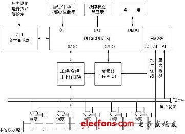
Figure 1. Block diagram of constant pressure water supply
2. System overview:
The system is composed of four large pumps (22KW) and one small pump (5.5KW); the PLC part is composed of the CPU226 of Siemens programmable controller S7-200 series, and the text display TD200; the inverter uses Mitsubishi FR-A540 series, power 22KW.
The user's required domestic water pressure, fire water pressure, operating mode and other parameters are set on the TD200 text display. The pressure sensor converts the user's pipe network pressure into a 0-10V standard signal and sends it to the PLC analog module EM235. The PLC passes the sampling program And the PID closed-loop program and the user set pressure form a closed loop. After the calculation, it is converted into a PLC analog output signal and sent to the inverter to adjust the speed of the pump motor to achieve the purpose of constant pressure water supply.
The system has the function of accumulating the running time of each pump, and it can be powered off and stored in the PLC data area. 1 # small pump is started at every start. When the water consumption exceeds the water supply capacity of one pump, the PLC realizes the delayed upward switching of the pump through the program. The switching principle is that the largest running pump that is not currently running has the least cumulative running time. ; When the pressure exceeds, the PLC realizes the delayed downward switching of the pump through the program. The switching principle is that the currently running large pump will be withdrawn first after the longest running time. Until the set pressure is met. The ultimate goal pursued is constant pressure.
When the water supply load changes, the output voltage and frequency of the frequency converter automatically adjust the pump motor speed to achieve constant pressure water supply.
The system can also automatically supply water regularly through the PLC's real-time clock. The user can set up a maximum of 6 segments per day on the TD200 (the number of segments can also be set), such as 6:00 to 8:30 in the morning and 11:20 to 1:30 at noon Wait.
The system can dynamically display various parameters, such as set pressure, operating pressure, water level height, operating mode, real-time time, calendar, running time accumulation of each pump (accurate to seconds), operating status, fault information, etc. In order not to make the TD200 screen in the system appear rigid, control the TD200 screen in the PLC program to switch regularly and display dynamically;
The system also has fault self-diagnosis function. If there is overload, phase loss, short circuit, sensor disconnection, sensor short circuit, water level lower limit, water pressure is too high, water pressure is too low, inverter failure, etc., there will be sound and light alarm, TD200 At the same time, it displays the type of failure, notifies the equipment maintenance personnel to deal with it, and can remember the time and shift of the failure, so as to trace the cause and related responsibilities
Dc Motor Ceiling Fan,Direct Current Ceiling Fans,Smart Dc Motor Ceiling Fan,Dc Motor Ceiling Fan With Light
Jiangmen MagicPower Electrical Appliances Co.,Ltd. , https://www.magicpowerfan.com