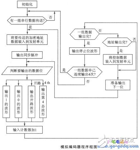
The serial data output waveform for each set of the VD5026-4 consists of a synchronization pulse, a 12-bit encrypted address along with control data, and a single stop bit. The sequence of the code pulses is AO to A7, followed by A8/DO to All/D3. Each group of serial data is transmitted at least four times. Once the serial data format, verification method, pulse period, duty cycle, and their corresponding relationships are understood, an application program can be developed according to the encoding pulse output requirements, enabling the microcontroller to function as an encoder. The block diagram of the analog encoder is illustrated below.
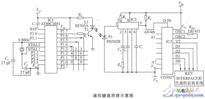
This infrared remote control keyboard, designed using this technology, has been successfully applied in a "color remote monitoring system." The working principle of the remote keyboard is shown below. The circuit uses a single-chip microcontroller, the AT89C2051, which is a cost-effective and widely used device. It is based on the 80C31 core and fully compatible with the MCS-51TM architecture. The chip includes 2 KB of reprogrammable flash memory, capable of being erased and rewritten up to 1,000 times, with data retention for up to 10 years.
The VD5027 decoder provides 4-bit data output, allowing it to represent 16 different states, which is sufficient for a 3×4 keyboard configuration. When the MCU detects a key press, it generates a corresponding code pulse. This signal is modulated with a 38 kHz carrier wave and transmitted via an infrared emitting diode (SE303A). The received infrared signal is converted into an electrical signal by an infrared receiving diode (PH302B), then amplified by the CX20106 infrared receiver module, resulting in a pulsed electrical signal.
After shaping and amplifying the signal, it is restored to the original encoded pulse that corresponds to the pressed key. This signal is then sent to the 14-pin DIN input terminal of the VD5027 decoder. Upon receiving the first set of encoded pulses, if they match the pre-set address in the VD5027, the four-bit data code (DO-D3) is stored in the internal register and converted from serial to parallel format. When the second identical pulse sequence arrives, the address is verified again. If both the address and control data match, the internal logic circuit of the VD5027 sends a control signal, transferring the data from the register to the DO-D3 output pins.
At the same time, the TV terminal switches from a low level to a high level, indicating that the decoding process is valid. Once the host receives this valid decoding signal, it reads the DO-D3 output from the VD5027, decodes the key value, and performs the corresponding operation accordingly.
Super Tweeter Bullet,Tweeter Driver,Speakers For Concert Speakers,Speakers For Performances
NINGBO RFUN AUDIO TECHNOLOGY CO.,LTD , https://www.mosensound.com