Accelerometers are widely used in various metering systems to measure acceleration, which is the rate of change of velocity over time, as well as to detect inclination. Inclination refers to the angle between the object's longitudinal axis and the vertical direction relative to the Earth's surface. Tilt measurements are typically considered as "direct current" or steady-state readings. While theoretically, acceleration could be steady, in real-world applications, it often occurs as a transient event.
For non-tilted environments where only short-term acceleration is expected, piezoelectric sensors or piezoelectric film sensors can be employed. These types of sensors have an equivalent AC voltage source in series with a capacitor, along with other reactive components that create secondary effects, which we won’t delve into here. Typical capacitance values range from hundreds of picofarads to a few nanofarads. Due to this capacitive coupling, such devices cannot provide stable, long-term tilt measurements.
The equivalent capacitance, combined with the input shunt resistor or subsequent amplification circuit, forms a single-pole high-pass filter (HPF). A higher shunt resistance results in a longer time constant, allowing for more accurate measurement of acceleration over a longer period before the HPF begins to attenuate the signal.
From a practical standpoint, choosing a 1 GΩ resistor is common. However, due to its high value, the operational amplifier used must have extremely low bias or leakage current—ideally up to 1 pA—to avoid introducing errors into the system.
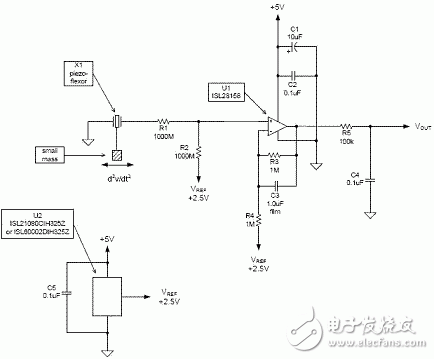
Figure 1 shows a practical circuit design. The piezoelectric film sensor is labeled as X1. In the prototype, an LDTM-028K device was used. One end of the sensor is exposed to a small amount of gravity, while applying a larger load increases sensitivity. The sensor is connected to the non-inverting input of op amp U1 through R1, which protects the op amp from overvoltage caused by sudden high accelerations, such as impacts. R1 also helps reduce the signal amplitude from X1. In this setup, R1 is set to 1 GΩ. R2 acts as the input shunt resistor. With a leakage current of 1 pA flowing through R2 (also 1 GΩ), a 1 mV bias voltage is generated, which is added to the actual op amp’s bias voltage. R2 is connected to a 2.5V reference to set the quiescent output level of the op amp. The chosen op amp is the ISL28158, known for its ultra-low input current. It is powered by a +5V DC supply. The DC gain is determined by R3 and R4, resulting in a gain of +2 V/V. A 1 μF capacitor (C3) serves as a low-pass filter to suppress high-frequency vibrations. Film capacitors are preferred here because ceramic types may introduce unwanted piezoelectric effects, commonly referred to as the "howling effect." Additional filtering can be achieved by adding another pole at the op amp output, using R5 and C4 as shown in the diagram.

When mounting X1 on the board, ensure that gravity acts on the underside of the board, causing the sensor to bend in the direction of the acceleration being measured. This orientation is crucial for accurate tilt detection and reliable performance in dynamic environments.
cbg oil vapes
Shenzhen Yingyuan Technology Co.,ltd , https://www.yingyuanvape.com