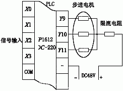
This article introduces a method for directly controlling a stepper motor using a programmable logic controller (PLC), as illustrated in Figure 2. The main advantage of this approach is that it significantly reduces the workload during system design, eliminates interface signal compatibility issues, and enhances the overall reliability of the system. The control system consists of a PLC and a stepper motor. As an industrial control computer, the PLC has become increasingly powerful, capable of not only switching logic control but also closed-loop process control. It can also be integrated with other computers to form a multi-level control system.
With the advanced capabilities of the PLC, various command pulse controllers from different systems can be managed through distinct PLC programs. However, for the functions of the ring pulse distributor and power amplifier, the PLC must meet two key requirements. First, the PLC should have real-time refresh technology to allow output signals at frequencies of several thousand Hz or higher. This ensures the ring pulse distribution operates at a high speed, fully utilizing the stepping motor's response capability and improving the system’s performance. Second, the PLC’s output ports must use high-power transistors to handle the pulse voltage and current required by the motor’s phase windings.
It is important to note that PLCs with relay or thyristor-based outputs cannot effectively drive the stepping motor, even if their software can achieve high-speed pulse distribution. This is because these devices are not suitable for fast DC switching, which is essential for providing the necessary pulse current to the motor windings. Therefore, they are unsuitable for direct control of a stepper motor. However, PLCs like the IP1612DC-220 from US IPM, which meet these requirements, can directly control the motor.

Figure 2: PLC direct control of a stepper motor
The author successfully applied this technique in the automatic bagging error compensation system of the ZXJ1000-C prestressed composite bag production line. In this system, the PLC receives the measured bag length error signal from the sensor. Based on the error and a compensation algorithm, the PLC program calculates the number of steps the motor needs to compensate and controls the motor through the Y9, Y10, and Y11 output ports. This enables the sequential switching of the three-phase winding of the motor, creating a rotating magnetic field that drives the motor. The motor’s rotation is then used to correct the bag length via a mechanical differential.
Since the stepper motor is an inductive load with low DC resistance, a current-limiting resistor is added to prevent excessive pulse current from damaging the PLC output ports, specifically the high-power transistors connected to Y9, Y10, and Y11. When these transistors are turned on and off in the sequence Y9-Y9Y10-Y10-Y10Y11-Y11-Y11Y9-Y9..., the motor rotates forward. Reversing the sequence results in reverse motion. This operation follows a three-phase six-step mode. Each step reduces the counter in the ring pulse distribution program. When the counter reaches zero, the pulse distribution stops, waiting for the next error input.

Figure 3: Specific application diagram
Conclusion: The error compensation system that directly controls the stepper motor via PLC offers excellent functionality, high flexibility, and strong reliability. This system was recognized with the National Science and Technology Progress Award. The method of directly controlling the motor with a PLC significantly reduces design workload, shortens development time, and holds considerable practical value within a specific range.
planar magnetics transformer,planar transformer altium,flyback planar transformer,coilcraft planar transformer
IHUA INDUSTRIES CO.,LTD. , https://www.ihuagroup.com