The HX711 is a high-precision 24-bit analog-to-digital (A/D) converter chip specifically designed for use in electronic weighing systems. Compared to similar chips, it offers a highly integrated solution by incorporating essential peripheral circuits such as a voltage regulator and an internal clock oscillator. This makes it more efficient, faster in response, and better at resisting interference, making it ideal for applications where accuracy is critical.
**Pin Functions:**
1. **VSUP**: Power supply for the on-chip voltage regulator (2.6–5.5V). If not used, connect AVDD.
2. **BASE**: Control output of the voltage regulator circuit (leave unconnected if not used).
3. **AVDD**: Analog power supply (2.6–5.5V).
4. **VFB**: Input control for the voltage regulator (ground if not used).
5. **AGND**: Analog ground.
6. **VBG**: Reference voltage output.
7. **INA-**: Negative input for channel A.
8. **INA+**: Positive input for channel A.
9. **INB-**: Negative input for channel B.
10. **INB+**: Positive input for channel B.
11. **PD_SCK**: Digital input for power-down control and serial clock.
12. **DOUT**: Digital output for serial data.
13. **XO**: Crystal input/output (leave unconnected if not used).
14. **XI**: External clock or crystal input; select internal oscillator by grounding.
15. **RATE**: Data rate control (10Hz or 80Hz).
16. **DVDD**: Digital power supply (2.6–5.5V).
**Analog Inputs:**
Channel A provides a programmable gain of 128 or 64, which corresponds to full-scale differential input voltages of ±20mV or ±40mV, respectively. This allows optimal use of the A/D converter’s dynamic range. Channel B has a fixed gain of 64 with a full-scale input of ±40mV and is often used for system parameter monitoring, such as battery voltage detection.
**Power Supply:**
The digital power supply (DVDD) should match the MCU’s supply. The HX711 includes an internal voltage regulator that supplies both the ADC and external Sensors. If not using the internal regulator, VSUP and AVDD must be connected to a low-noise analog power supply between 2.6–5.5V. No external capacitor is needed on VBG, and VFB should be grounded when unused.
**Clock Selection:**
If XI is grounded, the HX711 automatically uses the internal oscillator, resulting in a standard output rate of 10Hz or 80Hz. For higher precision, an external clock or crystal can be connected to XI and XO. In this case, the internal oscillator is disabled, and the output rate becomes accurate based on the crystal frequency. An external clock signal can be as low as 150mV, and a 20pF DC-blocking capacitor is recommended.
**Serial Communication:**
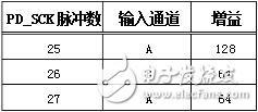
The HX711 communicates via the PD_SCK and DOUT pins. When DOUT is high, the chip is not ready to output data. Once DOUT goes low, 25–27 clock pulses are required to read out the 24-bit data. The first pulse reads the most significant bit (MSB), and the last pulse sets the next channel and gain. After changing the channel or gain, the ADC needs four cycles to stabilize before valid data is output.
**Reset and Power-Down:**
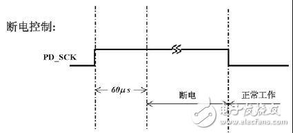
Upon power-up, the chip resets automatically. The PD_SCK pin controls the power-down mode: if it stays high for over 60μs, the chip enters power-down. When returning to low, the chip resets and resumes normal operation. After reset or power-down, the default is Channel A with a gain of 128. It takes four data cycles for the ADC to stabilize before valid output is available.
3 Phase Biogas Generator,1600KW Gas Turbine Generators,1600kW Biogas Gas Powered Generators,1600kw Biogas Generator Set
Jinan Guohua Green Power Equipment Co.,Ltd. , https://www.guohuagenerator.com