Analysis of Automatic Gain Control (AGC) Circuit of Color TV Receiver
This article introduces in detail the design and analysis of AGC (AutomaTIc GainContr01) circuit of color TV receiver.
In the color TV transmission system, due to the influence of different receiving environments or external interference and aging of the device, the strength of the received signal may vary greatly. When the signal is weak, the contrast of the image becomes smaller, the definition is poor, and the synchronization is unstable, making it impossible to image. The strong signal will cause the post-amplifier to enter the saturation and cut-off regions, resulting in severe signal distortion, and the sync pulse will be cut off, and a good image will not be obtained. This will affect users to watch TV programs normally.
1 Automatic Gain Control (AGC) circuit http: //
The automatic gain control (AGC) circuit plays an important role in early discrete and small-scale integrated circuits, or in today's ultra-large-scale integrated circuits, and generally includes the following aspects: image amplitude control circuit; sound amplitude control circuit; color Degree signal control circuit.
The working principle of the automatic gain control (AGC) circuit is shown in Figure 1. Set a reference level (U base). Through the detection circuit, the gain of the amplifier circuit is automatically adjusted according to the actual situation of the signal level, so that the output is stable at the reference On the level, that is UOUT≈U base. 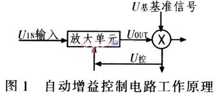
2 Trouble Analysis of Color TV Receiver If the control circuit of the color TV receiver fails or fails, the TV may have malfunctions such as no picture, reverse picture, noisy picture, small or distorted sound, no color or tint. Due to the different equipment used in the broadcast and television transmission system in various provinces and cities in China, the use of non-standard amplifiers during the transmission process results in different reception effects of TV receivers in different regions: some regions can receive normally, while some regions cannot. Receive, so AGC circuit design is very important.
2.1 The failure caused by the improper design of the intermediate amplifier circuit Konka A series TVs with Sanyo CA76810 as the main device have the phenomenon that the upper part of the image is twisted and the field is out of synchronization. After actual operation check, when using this series of TVs to receive wireless signals. There is indeed image twisting and out-of-sync phenomenon, and the oscilloscope is used to observe the video output signal. The line and field synchronization signals are compressed, that is, the amplitude is lower than the standard signal.
However, when using Konka A series TV sets to watch more standard cable signals, the above failures did not occur. Therefore, it can be concluded that it is caused by a non-standard TV signal, and the TV signal has seriously deviated from the national standard. Figure 2 is the connection diagram of the external circuit of Konka A series TV. 
Since the synchronization signal has been compressed, the only way for non-standard signals is to improve the image intermediate frequency amplification circuit, that is, by changing the capacity of the AGC filter capacitor to change the starting point and starting time of the middle amplifier circuit, so that it is separated The TV signal is relatively standard, and the redisplayed image can be normal and stable within the controllable range of the TV. Through the test, the C234 was changed from 68 nF to 20 nF, and the fault disappeared. The TV reception function is normal, and the signal reception is stable.
2.2 The AGC circuit causes the crash and data loss during TV white balance debugging. The second-generation super TV dominated by the ultra-large device produced by Konka, the core device is produced by the German Weike company, the model is VCT3801, VCT3803. This series of devices combine CPU and decoder into one, which greatly simplifies circuit board wiring and facilitates mass production. However, in actual production, there was a sudden crash during automatic white balance debugging, and the data loss of the color TV after debugging several times, and the picture appeared color cast. As a result, the production efficiency is reduced to only 50% of normal production. Even barely debugging a normal color TV set has serious quality risks.
1) White balance automatic debugging principle Due to the use of bus technology, the CPU will automatically detect the video and R, G, and B signals when the S series TV using the second generation of super devices is turned on, and make appropriate adjustments to ensure bright and true colors . The three signal amplitude data of R, G, and B are stored in the memory. The memory data is determined by the white balance automatic adjustment system before the television is shipped from the factory. Figure 3 shows the block diagram of the white balance automatic adjustment system. 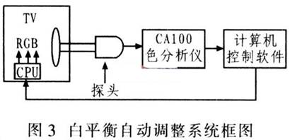
In Figure 3, the CAAl00 color analyzer processes the color temperature coordinates of the TV detected by the probe, and obtains (x, y) values. The (x, y) values ​​are sent to the corresponding control software of the computer, and the values ​​processed by the software are processed. Compared with the reference (x, y) value, a difference value is generated, and the required R, G, and B amplitudes are determined by software conversion, and then sent to the TV CPU. The CPU immediately adjusts the video signal R, G, and B amplitudes, and continuously loops. Until the (x, y) value detected by the probe is the same as the reference value, the computer stops automatic adjustment, and writes the amplitude data of R, G, and B into the memory at this time.
2) Cause analysis of S series machine failure After the failure occurs, due to the automatic control of the computer, the original reason for the failure may be: the configuration of the computer host is too low; the failure of the color analyzer; external interference; the communication between the computer and the TV CPU is impeded. But through the failure detection one by one, basically eliminate the above reasons. Therefore, the mid-range processing of the S series machine uses TDA4472. By adjusting the RP120 potentiometer, the device will automatically output the RF-AGC voltage. However, because the RP120 potentiometer production is inconsistent with the position of the middle brush, the RF-AGC voltage output by the TDA4472 is different In turn, the amplitude of the video signal is different. Because the amplitude of the video signal is inconsistent, the CRT brightness of each color TV is inconsistent.
In order to accelerate the white balance debugging speed, the S series TV sets a software learning function in order to speed up the white balance debugging. That is, during debugging, the system software automatically extracts the R, G, and B data of the previous TV and adjusts based on this. In this way, due to the inconsistent brightness, the system software has an automatic learning function, which causes the system software to enter a blind zone during debugging, which may exceed the control range of the system software. Once exceeded, the whole machine will suddenly crash. Even if it is barely debugged normally, it is very easy to cause data loss and color cast due to the edge of control. In order to avoid the above phenomenon, the RF signal adjustment is changed to the AV signal adjustment. Avoid the influence of the AGC circuit on the video signal, so that the difference between individuals during mass production is not very large, and is within the control range of the CPU.
Through the above adjustment, the failure phenomenon in the white balance adjustment process of the S series machine no longer appears, which greatly improves the production efficiency and eliminates the hidden quality problems. Therefore, no matter whether it is in production or in the process of not counting the products, we must attach great importance to the role of the AGC circuit.
3 Conclusion This article introduces the analysis of the application of AGC circuits in color TV receivers. Carry out detailed analysis of the faults that have occurred, and give corresponding solutions and measures. This greatly improves the production quality and efficiency of color TV sets. Therefore, the automatic gain control circuit plays an important role in the production of color TV.
LC1-D series AC Contactor is a kind of econimic products.It can be worked in different quality lever. Big difference for each quality level depend on the raw material and silver contact.This model Magnetic AC Contactor can match any quality level demand in the market. LC1-D series magnetic contactors are exact copy one of the most advanced big company schneider model. The quality and design are most reasonable which certified by the user in the market for a long time.
The magnetic Contactor is suitable for using in the circuits up to the rated voltage 660VAC 50Hz or 60Hz, rated current up to 95A, for making and breaking and frequently start, controlling the AC motor. Combined with the auxiliary contactor group, air delayer, machine interlocking devices etc. It is combined into the delay contactor, mechanical interlocking contactor, start-delta starter, with the Thermal Relay, it is combined into the electromagnetic starter.

Economic AC Contactor,Motor Control Contactor,Industrial Use AC Contactor,Motor Control AC Contactor
Ningbo Bond Industrial Electric Co., Ltd. , https://www.bondelectro.com