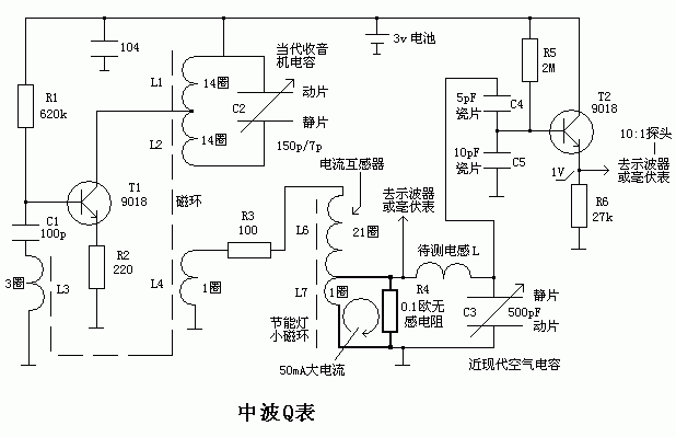
Principle: R4 outputs an ultra-low impedance signal voltage source at both ends, which is connected in series in the LC resonant circuit. When the circuit resonates, the inductive reactance and capacitive reactance of L and C are canceled, leaving only the R4 and the loss resistor r of the LC resonator in series. And the voltage across R4 is the voltage across r. Thus, we only measure the voltage U1 across R4, and we can get the voltage across r is also U1. Then measure the voltage U2 across C3, and finally Q=U2/U1.
This article refers to the address: http://
Why R4 is designed to be so small. In fact, it is also possible to use a larger one, that is, 1 Euro can be used. At this time, R3 should be increased to reduce the excitation current so that the voltage across R4 is not too high. A disadvantage of the voltage across R4 is too high. That is, in the high Q circuit, the voltage U2 across C3 is too high and will exceed the dynamic range of T2. In addition, from the two ends of L7, R4 and r are connected in parallel, then there is a disadvantage that R4 uses 1 ohm, that is, the high Q circuit has very small r, the current mainly flows through r instead of R4, so it flows through the inductor to be tested. The current of L is relatively constant, then the voltage across C3 near the resonant frequency is relatively stable. At this time, we must measure the voltage across R4 in turn to know whether it is accurate or not, and the voltage across R4 is relatively small and difficult to measure. So it is recommended that R4 be smaller. However, R4 should not be too small, otherwise the excitation is not enough. If the Q value of the large loop antenna is measured, the radio signal of the large loop induction may be stronger than the excitation signal, and the measurement is interfered.
L4 has only one revolution, and the proportional relationship with L1 is 1:14. Therefore, L1 is connected to the R3 load of 100 ohms, which is equivalent to the 14*14*100=19.6 kohm load connected to both ends of L1, which will not affect the oscillator. normal work. The voltage across L4 is 0.4 volts, which refers to the peak-to-peak voltage, which is equivalent to the AC peak voltage of 0.4/2 = 0.2V. Unless otherwise specified, the AC signal refers to the peak-to-peak voltage or current. R4 is equivalently converted to L6, which is equivalent to 0.1*20*20=40 ohms, then the current flowing through R3 is 0.4V/(100+40)=0.0028mA. After passing through the current transformer, the current on L7 is about 0.0028*20=56mA, then the voltage across R4 is 56mA*0.1Ω=5.6mV. Of course, when actually measuring the Q value of the coil, the voltage across R4 is subject to actual measurement. The current of the L7 and R4 loops is very large, which will adversely affect the circuit. Therefore, the lead of the loop is shorter. If the lead is made long, the inductance of the lead circuit will affect the current conversion effect of the transformer.
T2 is an impedance converter, and the relevant circuit should be farther away from the oscillator and the transformer to avoid interference. In addition to the connection of the positive and negative poles of the power supply, all of the circuits are connected overhead, so that the distribution parameters are the smallest.
In the audio power amplifier circuit, some zero-ohm resistors are used, and those resistors that are not in the form of coils can be found. I used two 0.22 ohm resistors in parallel to get a 0.11 ohm non-inductive resistor.

Then the current flowing through L6 is about
If it is a high Q coil, the pure part of the load impedance of C4 should not be ignored, and it is best to correct it during calculation. This pure resistance is equivalent to approximately 8M ohms at both ends of C3, and the loss of the ceramic capacitor may also be estimated. I have not found out the loss of the ceramic capacitor.
Small amount of waveform distortion: Due to the heavy load, the output waveform is a bit distorted, but it is relatively slight and will not affect the accuracy of the voltage measurement across R4.
Non-inductive resistance problem: Adjust C2 to change the signal frequency. If the voltage across R4 changes, it means that R4 is not non-inductive and should be replaced.
The primary inductance of transformer L6 is approximately 400uH. The core is made of a magnetic ring inside the energy-saving lamp, which is a high-magnetic high-frequency ring.
We can provide hardware design services for customers. After the adoption of the feasibility plan.We can complete the design of Circuit Board Layout, and export the gerber file, BOM and so on. And then start customizing the Printed Circuit Board and PCBA for the customer's product.
Our design software: Altium Designer/ Genesis/ Eagle/ P-cad/ Protel-99SE/ CAM350/ Power PCB /AutoCAD and etc.

PCB Design,Electronic PCB Design,One-Stop PCB Design,Electronic Development PCB Design
Orilind Limited Company , https://www.orilind.com