This article describes a solar cell phone charger
This article refers to the address: http://
The working principle of the circuit is briefly described as follows:
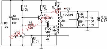
The triode VT1 is a switching power supply tube, and it is composed of a self-excited oscillation circuit with T1, R1, R3, and C2. After the input power is applied, the current flows through the starting resistor R1 to the base of VT1, turning VT1 on.
After VT1 is turned on, the transformer primary winding Np is added with the input DC voltage, its collector current Ic increases linearly in Np, and the feedback coil Nb generates 3 positive and negative 4 induced voltages, so that VT1 is extremely positive and the emission is extremely negative. Positive feedback voltage, this voltage is injected into the VT1 base current through C2 and R3 to further increase the collector current of VT1, and the positive feedback generates an avalanche process, so that VT1 is saturated and turned on. During the VT1 saturation conduction, T1 stores magnetic energy through the primary winding Np.
At the same time, the induced voltage charges C2. As the C2 charging voltage increases, the VT1 base potential gradually becomes lower. When the base current change of VT1 cannot satisfy its saturation, VT1 exits the saturation region and enters the amplification region.
After VT1 enters the amplification state, its collector current decreases from the maximum value before the amplification state, and a negative voltage of 3 negative and 4 positive is generated in the feedback coil Nb, so that the base current of VT1 decreases, and the collector current decreases accordingly. The feedback once again showed an avalanche, and VT1 quickly closed.
After VT1 is turned off, the energy stored in the transformer T1 is supplied to the load, and the 5 negative and 6 positive voltages generated by the secondary winding Ns are rectified and filtered by the diode VD1, and the DC voltage is obtained on the C3 to charge the mobile phone battery.
When VT1 is cut off, the DC power supply input voltage and the Nb-induced 3 negative and 4 positive voltages are reversely charged to C2 via R1 and R3, and the VT1 base potential is gradually increased to make it re-conduct and flip again to reach saturation state. The circuit repeats the oscillation.
R5, R6, VD2, VT2, etc. form a voltage limiting circuit to protect the battery from being overcharged. Here, the 3.6V mobile phone battery is taken as an example, and its charging limit voltage is 4.2V. During the charging process of the battery, the battery voltage gradually rises. When the charging voltage is greater than 4.2V, the voltage-stabilizing diode VD2 starts to conduct after being divided by R5 and R6, so that VT2 is turned on, and the shunting effect of VT2 reduces the base of VT1. The pole current, which reduces the collector current Ic of VT1, achieves the effect of limiting the output voltage. At this time, the circuit stops charging the battery with a large current, and the battery voltage is maintained at 4.2V with a small current.
Component selection and installation and commissioning
VT1 requires Icm>0.5A, hEF is 50-100, 2SC2500, 2SC1008, etc., VD1 is a Zener diode with a regulated voltage of 3V.
The high-frequency transformer T1 should be self-made, using E16 ferrite core, Np with φ0.21 enameled wire wrapped around 26åŒ, Nb with φ0.21 enameled wire wrapped around 8åŒ, Ns with φ0.41 enameled wire wrapped around 15åŒ. When winding, pay attention to the starting end of each coil, so as not to make the circuit not vibrate or the output voltage is abnormal. During assembly, a plastic film with a thickness of about 0.03 mm is placed between the two cores as a core air gap.
The solar panel uses four silicon solar panels with an area of ​​6 cm x 6 cm, and its no-load output voltage is 4V. When the operating current is 40mA, the output voltage is 3V. Since the operating efficiency of the DC converter increases as the input voltage increases, four solar panels are used in series, and the input voltage of the circuit is 12V. Readers can determine the number and method of connection based on the solar panel specifications you can purchase.
The parameters of the other components are shown in Figure 1.
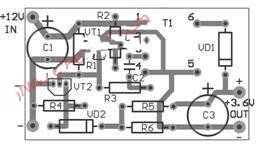
The printed circuit board is shown in Figure 2 and measures 45 x 26 mm2.
After the installation is completed, the solar panel is connected and placed in the sun. The output voltage of the circuit is about 4.2V when the load is no load. When the no-load output voltage is higher than 4.2V, the resistance of R5 can be appropriately reduced, and vice versa. The resistance of R5. The operating current of the circuit is related to the intensity of sunlight. When it is normal, it is about 40mA. At this time, the charging current is about 85mA.
Led Flood Light is a good
choice for outdoor lighting whether for industrial or commercial lighting, such
as factories, construction sites, parking lots, stadiums, shopping malls, etc.
You can even put a low-power floodlight outside your home.
Safety Flood Light. It will bring you a bright night under the lighting of our
durable, energy efficient and safety floodlight.
Power of flood light could be various, from 3watt to 1000watt. Good design with
qualified quality makes your project work perfectly.
Led Flood Light,Flood Light,Led Flood Light Outdoor,Led Flood Light 200W
ZHONGSHAN G-LIGHTS LIGHTING CO., LTD. , https://www.glightsled.com