At the heart of the Chevrolet Volt sedan has a sophisticated power pack management system that ensures the safety and reliability of a multi-unit lithium-ion battery pack that powers the Volt drive train.
This article refers to the address: http://
The battery monitoring board within this management system uses two critical subsystems to reliably monitor battery health and provide digital results to the host processor, which then coordinates the overall operation of the system. Separate the two subsystems to see a signal interface that ensures good isolation between the high voltage battery detection circuitry and the onboard communication components.
In this dismantling report, we reviewed the challenges associated with the management of high-voltage lithium-ion battery packs in automotive applications and discussed how the overall architecture of the Chevrolet Volt battery management system can meet these challenges. In particular, we discussed the requirements for lithium-ion battery monitoring, focusing on the architecture and components used in the battery monitoring subsystem, digital communication subsystem, and isolation interface. We also looked at the components selected for this design, including custom ASICs, Freescale's S9S08DZ32, Avago's ACPL-M43T and Infineon's TLE6250G. Finally, we discuss the advantages of this specific solution for mission-critical battery pack management and weigh the possible alternatives that can meet similar design challenges.
To provide more information on the isolation of automotive battery management systems, we also offer three series of in-depth video interviews.
Part 1: Introduction to the role of isolation in automotive battery management systems;
Part 2: Discuss some of the considerations when selecting devices for these applications;
Part 3: Explore the use of isolation devices in the Chevrolet Volt battery management system.
Electric car challenge
The Chevrolet Volt is the first battery-powered electric vehicle (EV) to be produced, which can travel nearly 40 miles on battery alone. When the battery is close to the low limit, the gasoline engine can be activated to generate additional power, which in turn increases the vehicle's range to hundreds of miles. In the center of the Volt sedan, there is a lithium-ion battery pack with a length of 1.8 meters and a weight of 181 kilograms, which can generate 16 kWh of power, enough to start the drive motor, power the passenger equipment, and power the complex battery management system. The complexity of this management system is comparable to that of a flight system.
IBM senior vice president Robert LeBlanc pointed out that the Volt software content has 10 million lines of code, exceeding the 7.5 million lines of code that is said to fly the US DOD F-35 Lightning 2 joint combat aircraft - the software itself exceeds the current jet fighter Three times the code size, according to the US Government Accountability Office. Although LeBlanc may have chosen a less controversial system for comparison, the Volt does raise a lot of controversy about itself. Maybe no other car has received the attention like Volt. In fact, when the Volt test vehicle caught fire in a test collision after several weeks of parking, the incident immediately caught the attention of government agencies and triggered a GM repurchase – even after the “actual collision accident†did not occur. The battery-related fire problem, the National Highway Traffic Safety Administration said.
Ultimately Volt's success depends on the degree of public acceptance – and its function. To achieve this goal, when designing the Volt, GM worked with IBM to simulate the "system of the system" performance in the Volt. By using a detailed model of critical systems, IBM software not only validates behavior, but even generates key parts of the software code used in the Volt system. This method of code generation and system modeling is critical to ensuring the performance of the Volt battery management system, as it requires complex algorithms to ensure optimal lithium-ion battery performance and longevity; in fact, optimizing the performance of this battery is still It is a research topic of great concern to industry, government and academia. For Volt, ensuring battery performance allows the final multi-board design (Figure 1) to integrate the work of multiple embedded systems into a single, complete system that meets the travel distance, safety, and safety offered to Volt Li-Ion battery packs. Performance and longer life requirements.
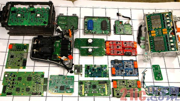
Figure 1: The Chevrolet Volt Battery Management System divides all functions into multiple subsystems implemented in multiple PCBs. The focus of this disassembly is the battery interface control module - the red, blue and green boards in the second column from the right. (provided by UBM TechInsights)
Lithium-ion battery characteristics
The complex systems required to meet Volt performance, safety and reliability requirements are directly related to the characteristics of lithium-ion batteries. When a lithium ion battery is discharged, lithium is ionized in a (typical) graphite anode, and lithium ions enter the electrolyte and pass through the separator to reach the cathode, thereby generating a charge flow. In contrast to the charging process, lithium ions enter the electrolyte from the cathode and flow back through the separator back to the anode.
The performance and reliability of this chemical process depends on the temperature and voltage of the battery. In a low temperature environment, the chemical reaction is slow, thus lowering the battery voltage. As the temperature rises, the reaction rate increases until the lithium-ion battery component begins to decompose. When the temperature is higher than 100 ° C, the electrolyte begins to decompose and release gas, which will cause accumulation of pressure in the battery without the pressure release mechanism. At sufficiently high temperatures, lithium-ion batteries may experience thermal runaway, accompanied by decomposition of oxides and release of oxygen, which in turn accelerates temperature rise.
Accordingly, keeping the lithium-ion battery in optimal working condition is a key requirement of the Volt battery management system. The problem for Volt engineers is to ensure reliable data collection and analysis to properly monitor and control the state of the lithium-ion battery in the car – a problem that is exacerbated by the nature of the lithium-ion battery itself.
One feature of our lithium-ion battery technology is that at a given temperature and output current value, a lithium-ion battery can maintain an approximately flat voltage output in the middle of its capacity range (Figure 2). While this feature enhances the advantages of lithium-ion batteries as an energy source, it also complicates engineers' attempts to use simple battery voltage measurements to provide users with the means to maintain battery power or state of charge (SOC). For Volt car drivers, accurate SOC measurements are the key to accurately estimating the remaining mileage of a car. In fact, in the emerging electric vehicle market, “mileage anxiety†is a key factor hindering the popularity of electric vehicles and rising sales, so it is very important to accurately describe the SOC.
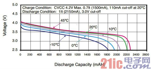
Figure 2: At a given temperature and discharge current value, a lithium-ion battery like the Panasonic CGR18650CG has a nearly flat output voltage in the middle of the discharge range. This is an advantage for energy, but adds design complexity to engineers who need to accurately measure state of charge (SOC). (provided by Panasonic Corporation)
In addition, keeping the SOC within a certain range is also important for extending battery life. Too low or too high a state of charge of the battery will result in performance degradation faster than maintaining the intermediate value, which is generally empirically derived. If full discharge is allowed, the composition performance of the lithium ion battery will begin to deteriorate and cause permanent damage. If the Li-Ion battery is allowed to charge above the recommended upper voltage limit, the battery may overheat or permanently deform the structure.
In the Volt, General Motors engineers built a safety SOC window of 58% to 65% and can adjust to the driving mode. In the normal driving mode, the lower limit can be set to 30% SOC. In the "mountain driving" mode, the lower limit can be set to a higher 45% to ensure that there is enough power to go uphill and extend the driving time. When the Volt reaches the appropriate SOC lower limit, the car's gasoline engine will be activated to extend the travel distance.
Estimated state of charge
Since the state of charge (SOC) measurement of lithium-ion batteries is not very reliable, engineers can only perform SOC estimation, generally using current-based or voltage-based methods.
Current based methods provide the most accurate results. Such a method tracks the change in charge, essentially calculating the number of coulombs added to the battery during charging or the number of coulombs subtracted during the discharge period, and then determining the SOC of the battery relative to the fully charged state. However, the loss of self-discharge or the inefficiency of the battery itself may cause errors in the "coulomb counting" method. In addition, because continuous monitoring is impractical for many applications, coulomb counting requires the use of sampling methods. In automotive applications, this method must be fast enough to automatically track the rapid discharge associated with acceleration and the fast charging associated with regenerative braking.
The voltage-based method uses the transient voltage output of the battery as a basis for further calculations to estimate the SOC, taking into account variations in battery temperature, aging, current output, and discharge rate. The voltage method provides accurate SOC estimation results when used with accurate characterization data for single-cell Li-Ion batteries under a variety of operating conditions. For product vehicles like Volt, the maintenance process requires precise battery characterization and the need to provide specific tools and procedures that enable the battery management system to learn the capacity of new battery modules—or relearn battery capacity when necessary.
Lithium ion battery chemicals
Lithium-ion batteries contain a variety of chemicals, each with different characteristics in terms of energy density, efficiency, durability, and nominal battery voltage. LG Chem's batteries for Volt use our Mn spinel cathode lithium ion chemistry and a proprietary safety-enhanced separator, a ceramic-coated semi-permeable membrane. From the perspective of the industry, lithium-ion batteries are manufactured in a variety of forms, including the familiar cylinders; flat packages used in mobile phones; and rigid-plastic prismatic packages. The original LG Chem battery for Volt is available in a prismatic package.
As the analysts at UBM TechInsights and Munro & Associates described, the entire Chevrolet Volt battery pack consists of 288 prismatic lithium-ion batteries, which are packaged into 96 battery cells, which are ultimately measured by analysts. 386.6V DC system voltage. These battery unit groups are also combined with a temperature sensor and a cooling unit to form four main battery modules. A voltage detection line connecting each battery pack is terminated to a connector at the top of each battery module, and a voltage detection harness connects the connector to a battery interface module located at the top of each battery module. There are four color-coded battery interface modules that operate in different locations in the battery pack, corresponding to the low voltage, medium voltage, and high voltage ranges of the DC voltage offset of the four module groups.
Data from the battery interface module is passed up to the battery energy control module. The control module then communicates the fault condition, status, and diagnostic information to the hybrid drive control module, which acts as the primary controller to complete the vehicle-level diagnostics. At any time, the entire system will run more than 500 diagnostics every 0.1 seconds. Eighty-five percent of the diagnosis is focused on the safety of the battery pack, and the remaining diagnostics are used for battery performance and longevity.
Multi-layer circuit board
Subsequent analysis of battery performance began with a focus on the battery interface control module (Figure 3). This module uses a 4-layer PCB board with most of the components mounted on the top layer, as well as an orange battery connector and a black data communication connector. The top layer has a ground plane and some signal traces, and some traces are connected to the underlying layers through multiple vias. In the second layer, the power and ground planes are laid under the high voltage area of ​​the PCB. Layer 3 contains signal traces that pass under these areas. The other side of the PCB, Layer 4, is used for ground planes and signal traces and contains a few auxiliary components.
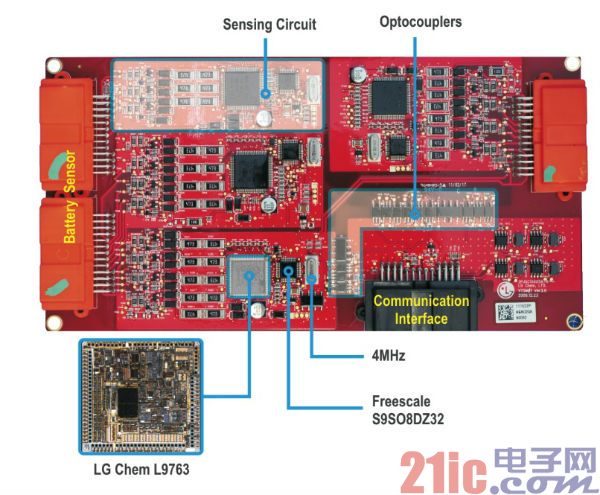
Figure 3: There are four battery interface control module PCBs in the Chevrolet Volt. Each PCB integrates multiple detection circuits and CAN communication circuits and is isolated by optocouplers located at the edge of the communication subsystem. (available from UBM TechInsights)
The black ATLPB-21-2AK PCB mount connector carries a 5V reference, low voltage reference, signal ground, CAN bus high speed serial data, CAN bus low speed serial data, and high voltage fault signals. The orange battery connector carries the battery module temperature signal, the low voltage reference, and the voltage sense line from the battery cell group.
Detection subsystem
At the heart of the battery interface control system is a sophisticated detection subsystem—a complete embedded system circuit that monitors the output voltage of each Li-Ion battery pack and the temperature of the battery pack. The battery voltage reaches the L9763 through the battery connector, an ASIC jointly developed by STMicroelectronics and LG Chem.
The L9763 ASIC can monitor up to 10 independent Li-Ion battery packs, battery-load-current monitoring via on-chip current sense amplifiers, and battery voltage monitoring via on-chip analog multiplexers and sample-and-hold circuits (Figure 4 ). The differential input of this device ensures millivolt accuracy measurements at large offset voltages, depending on the location of the battery cell in the battery pack. In addition, PCB designers can use trace layout technology, isolation technology, and the aforementioned ground planes to ensure signal integrity in this challenging environment.
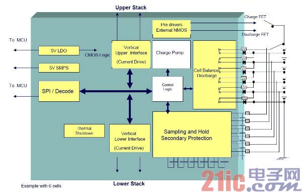
Figure 4: The L9763 ASIC includes on-chip circuitry for measuring the voltage and current of the Volt battery pack and balancing the charge in these cells through passive resistor cell balancing techniques. (Provided by STMicroelectronics)
Based on these measurements, the L9763's on-chip circuitry switches individual battery packs to an external resistor network to selectively discharge the battery, reducing stress due to large voltage differences. This simple passive technology provides a simple, low-cost solution for battery balancing, but loses efficiency because energy is lost to heat on the discharge resistor (Figure 5). An alternative battery balancing technique uses an active method to store the highest voltage battery and redistribute it to the lowest battery. This technique requires sequential switching between each cell and uses capacitors, inductors, or transformers to store or redistribute power. While active methods have the advantage of saving energy compared to passive methods, they increase system cost and complexity.
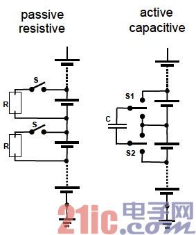
Figure 5: Passive battery balancing technology (left) switches high-voltage batteries to discharge resistors; active battery balancing techniques can accumulate power to capacitors (right) or inductors in turn, or use a transformer to distribute power to low-voltage batteries. (Provided by STMicroelectronics).
In order to charge or discharge a multi-cell lithium-ion battery pack, the design generally uses a constant current or constant voltage method. At this time, the charging system will use a pair of MOSFETs to reduce the charging current when the desired charging voltage is reached, or to increase the current during the discharging operation. . The L9763 provides a charge pump to drive power MOSFET devices. The L9763 transmits the measured data of the monitored lithium-ion battery to Freescale's S9S08DZ32 MCU via the SPI interface. The L9763 also provides a 5V LDO output to the MCU. For the overall battery management function, each L9763 device is linked via an on-chip interface and individually addressed by the main control unit via vertical daisy-chain communication.
Detection circuit MCU
As mentioned above, SOC estimation of lithium-ion batteries is a complex task that requires sufficient processing power. In this design, each detection subsystem has a L9763 ASIC and a Freescale S9S08DZ32 40-MHz HCS08 MCU with integrated 32kB flash, 2kB RAM and 1kB E2PROM. An external 4MHz oscillator provides a reference frequency for MCU clock operation.
In the GM-LG Chem design, the MCU needs to perform the operations required to estimate the SOC based on the voltage and current measurement data provided by L9763. Although the SOC algorithm is a proprietary algorithm, the hardware configuration and maintenance procedures suggest that these estimation algorithms can combine voltage-driven estimation using stored battery characterization data with more direct power measurement for temporary recalibration during charging. The use of a detailed system modeling environment described by IBM provides an ideal platform to help find the right data set for optimizing SOC calculations and to validate methods under widely sampled operating conditions.
HCS08's security features, such as a computer-operated watchdog timer, help ensure reliable operation and automatically generate a reset signal in the event of an unrecoverable application failure. Of particular importance in this application is the fact that the S9S08DZ32 has a complex on-chip CAN controller that can selectively power down or enter sleep mode when not in use (Figure 6). To help ensure predictable real-time performance, the on-chip controller integrates five receive buffers and forms a FIFO buffer, as well as three transmit buffers that allow for prioritization of outgoing messages.
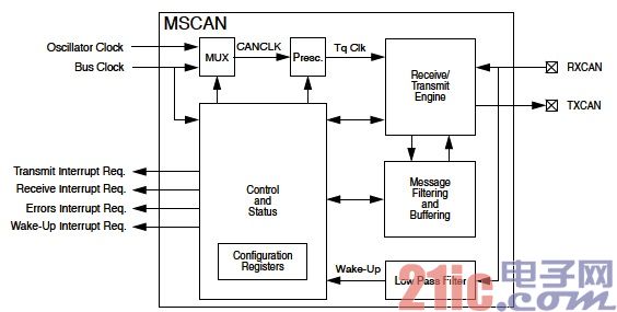
Figure 6: The on-chip CAN controller is a key factor in the construction of the battery interface control module detection subsystem using the Freescale S9S08DZ32 MCU. (provided by Fairchild Semiconductor)
Signal isolation
In the system of the Chevrolet Volt system, communication and control are the basis of automotive work, and Volt provides multiple networks for isolating and protecting individual subsystems. The complex algorithm described above requires management of individual lithium-ion battery packs and monitoring of battery packs within each of the detection subsystems on a particular battery interface control module. However, the critical data required for overall battery management is included in the CAN bus signal interface and high voltage fault signals. At the same time, system security and reliability depend on the safety isolation of the CAN bus network and the high voltage detection circuit. While isolation can be achieved in a variety of ways and components, harsh environments and multiple safety regulations make optocouplers the preferred solution for this type of application.
Optocouplers provide high common-mode noise rejection and are largely immune to EMC and EMI associated with electrical noise environments such as automobiles. In addition, these devices have very thick multilayer insulation that is very resistant to long-term DC voltage stress from the battery pack and rapid high-voltage transients that can occur during testing, charger connection/disconnection, and DC/DC conversion. it works.
When selecting such critical components, key requirements for automotive applications include proper packaging and operating voltage specifications. While performance metrics such as speed, data rate, and power consumption are still important, EMI considerations from fast switching times and large transient currents often limit the need for very high speed devices, and instead increase the adjustment slew. Rate and performance to further limit the flexibility requirements of EMI.
Automotive grade optocoupler
Avago Technologies' ACPL-M43T optocoupler provides isolation in the Volt Automotive Battery Interface Control Module PCB. The M43T is part of the Avago R2Coupler family of automotive-grade single-channel digital optocouplers in a 5-pin SO-5 Jedec surface mount package. To enhance insulation performance, Avago’s R2Coupler devices such as the M43T use dual bond wires to enhance critical function pads (Figure 7). In addition, the use of sealed automotive grade LEDs demonstrates extended reliability and a wide temperature range, which is much higher than optocouplers based on consumer LEDs. Avago devices for automotive applications are manufactured in accordance with the ISO/TS16949 quality system and are certified to the AEC-Q100 specification.
Figure 7: In automotive grade R2Coupler devices such as the ACPL-M43T optocoupler, Avago uses a double bond wire to reinforce critical function pads (shown in highlights). (provided by Anwar High Tech)
The ACPL-M43T is well suited to meet Chevrolet Volt battery requirements, including 567V continuous operating voltage, 6000V maximum transient overvoltage, 5mm creepage distance and 5mm pitch. The device's logic high or logic low output has a common-mode transient rejection of 30 kV/μsec at 10mA forward input current, which reduces the likelihood of transient signals from other automotive subsystems entering the CAN transmission network.
The 1M baud rate of the ACPL-M43T optocoupler is sufficient for this type of design. In addition, the device uses an open-drain output mode, and the designer can adjust the output slew rate to reduce the electromagnetic radiation that can be caused by fast switching in downstream components. The downstream fast switching elements include CAN transceivers, although their inherent EMI is relatively low in the CAN physical layer transmission protocol.
In the battery interface module PCB, the M43T device is located at the edge of the communication portion, which isolates the communication portion from the high voltage detection subsystem, which is further shielded by the ground plane in the deeper PCB layer. The isolated interface provides three independent M43T optocouplers for each of the three wires from each detection circuit—the Freescale S9S08DZ32 CAN Tx output pin, the MCU CAN Rx input pin, and the high voltage fault from the MCU. signal. For example, the output signal of the MCU CAN Tx pin will supply the embedded LED through the shielded signal layer in the PCB to the pin 1 anode of the M43T device and cause a change in state of pin 5 Vo (Figure 8). The isolated signal is then transmitted to the communication output stage circuit of the battery interface module.
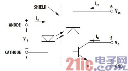
Figure 8: The Avago ACPL-M43T optocoupler is used to isolate the signal between the Freescale S9S08DZ32 MCU and the Infineon CAN transceiver. (provided by Anwar High Tech)
CAN physical signal
The Infineon TLE6250G CAN transceiver is located at the end of the communication signal chain and is an AEC-certified IC that provides physical cable and CAN protocol processors - here the CAN physical layer between the S9S08DZ32 MCUs (isolated by optocouplers) signal. The device's nominal CAN transfer rate is 1M baud, which handles the conversion between CAN_H and CAN_L signals on the differential signal line, as well as the CAN dominant and recessive bits transmitted and received by the S9S08DZ32.
The 8-pin TLE6250G includes the Tx, Rx, Vcc, GND, CAN_H, and CAN_L pins and two mode control pins: INH and RM. When the TLE6250G detects that the signal on the Rx pin changes from CAN idle state to CAN occupied state, the device will swap CAN_H high and CAN_L low (Figure 9).
This symmetrical change in state can effectively reduce EMI because the electromagnetic radiation caused by the rise of CAN_H can be balanced by the opposite direction of CAN_L.
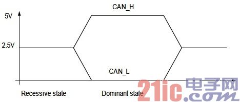
Figure 9: Symmetry changes in CAN_H and CAN_L in the CAN physical layer help reduce EMI. (provided by Infineon Technologies)
The TLE6250G device supports three modes of operation: normal, standby, and receive only. When the RM pin is set low, the device operates in receive-only mode, which is helpful for diagnostics. When the INH pin is asserted high, the device enters a low-power standby mode with both transmit and receive functions turned off.
Next generation system
The Chevrolet Volt is certainly one of the most complex distributed embedded system applications put into production in the commercial market, and its design is at the leading edge in many fields. Among the most important systems affecting the success of Volt and the popularity of the electric vehicle market, automotive lithium-ion batteries and related battery management systems demonstrate the increased importance of software and circuits in automotive applications. According to the recently released McKinsey market research report, by 2025, emerging lithium-ion technology can increase battery capacity by 80% to 110%, and the price will drop, so that the total cost of ownership of electric vehicles can be compared with conventional cars driven by internal combustion engines. Fight against each other. For engineers, the challenge remains as to discovering the full potential of emerging lithium-ion battery systems in the face of higher DC voltages, battery capacity, data rates and consumer expectations.
Doorbell speaker:
Doorbell speaker is a kind of micro speaker unit which uses a diaphragm made of Mylar material. Doorbell speakers are of ultrathin design and lightweight and clear voice. It is widely used in building security industry (e.g. intercom, video door phone, intelligent door control..)
There are two types of Mylar speakers from the shapes:
1) Round shapes, we have products from 10mm to 57mm in diameter.
2) Oblong shape, we have products in sizes of 1510/1712/1813-..


FAQ
Q1. What is the MOQ?
XDEC: 2000pcs for one model.
Q2. What is the delivery lead time?
XDEC: 15 days for normal orders, 10 days for urgent orders.
Q3. What are the payment methods?
XDEC: T/T, PayPal, Western Union, Money Gram.
Q4. Can you offer samples for testing?
XDEC: Yes, we offer free samples.
Q5. How soon can you send samples?
XDEC: We can send samples in 3-5 days.
Doorbell Speaker,Doorphone Speaker,Video Doorphone Speaker,Doorbell Wireless Speakers
Shenzhen Xuanda Electronics Co., Ltd. , https://www.xdecspeaker.com