The LTC3780 is a high-performance buck-boost switching regulator controller that can operate with input voltages either higher, lower, or equal to the output voltage. This flexible design makes it suitable for a wide range of applications where voltage levels may vary. It features a constant-frequency current-mode architecture, allowing for phase-lockable operation up to 400kHz. With an input and output voltage range from 4V to 30V (with a maximum of 36V), the LTC3780 supports seamless transitions between different operating modes, making it ideal for use in automotive, telecommunications, and battery-powered systems.
The operational mode of the LTC3780 is controlled via the FCB pin. For boost configurations, this pin allows selection between Burst Mode, Discontinuous Mode, and Forced Continuous Mode. During buck operation, the FCB pin enables switching between Skip Cycle Mode, Discontinuous Mode, and Forced Continuous Mode. These modes are designed to optimize efficiency under varying load conditions. Burst Mode and Skip Cycle Mode offer high efficiency during light loads, while Forced Continuous and Discontinuous Modes ensure stable, constant-frequency operation when needed.
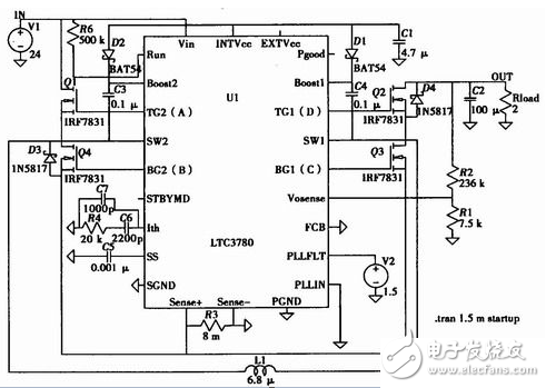
The LTC3780 includes a built-in power failure protection circuit, ensuring system reliability. It features an output overvoltage comparator and an internal foldback current limit circuit to prevent damage from excessive voltages or currents. Additionally, the Power Good output pin provides a signal when the output voltage remains within 7.5% of its intended adjustment point, offering a reliable indication of stable operation. A typical application setup is illustrated below.

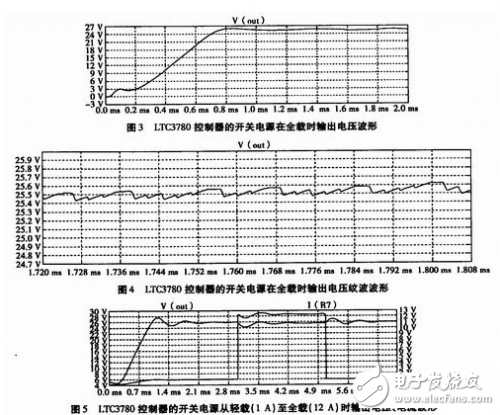
A 24V input, 26V output, 300W switching power supply was designed using the LTC3780 controller. After completing the initial design, the circuit was simulated using LTspice IV software. The schematic diagram of the simulation is shown in Figure 2. The voltage waveform and ripple at full load are presented in Figures 3 and 4, respectively. Furthermore, the output voltage and current waveforms from light load (1A) to full load (12A) are displayed in Figure 5, demonstrating the controller’s performance across a wide range of operating conditions.
48V Lithium Battery,lithium battery bicycle,Electric Bicycle Battery,lithium electric bicycle
Shenzhen Jentc Technology Co., LTD , https://www.phenyee.com