PSoC sensor application platform
In an embedded system, the control chip mainly processes two types of signals, one is a digital signal and the other is an analog signal. Analog signals usually come from sensors. It is not an easy task to obtain accurate signals from these analog sensors. The analog output signal usually has a relatively small amplitude, so a signal amplifier is required. After the signal is amplified, the noise will also be amplified, and an analog low-pass or band-pass filter is required for filtering. If multiple sensors are used simultaneously, an analog MUX is also required. In addition, it is possible to use comparators and D / A converters.
In traditional designs, the controller is only used to implement data processing, communication and control functions between systems. If your design also uses this traditional way, you will face some challenges. These challenges mainly come from separate analog devices and fixed-function MCUs. First of all, from the perspective of system design, with the acceleration of market changes and the increase of user requirements, a flexible hardware and software platform is necessary, and separate analog devices and fixed-function MCUs are far from meeting the constantly updated design requirements. And limited R & D time to market. Second, dealing with sensor noise requires a complex mixed-signal solution, usually requiring amplifiers, filters, ADCs, comparators, and DACs. For the traditional design, it is necessary to consider a lot of independent separation devices, which will become a burden in terms of product cost and production cost.
The highly integrated and flexible design of PSoC effectively addresses these challenges. What functions can PSoC achieve? The single-chip PSoC can realize the input and signal processing of various analog sensing signals at the signal input end, and at the same time, it can also realize the design of the capacitive touch sensing that is popular nowadays. In terms of control functions, PSoC can realize the control and power control of various fans and motors, and also supports a variety of complex communication interfaces. The application of PSoC is ubiquitous. Consumer electronics, white goods, medical, automotive, and industrial control products all have a place to use PSoC. At present, PSoC has more than 8100 customers worldwide and more than 400 million shipments.
What kind of system-on-chip is PSoC? PSoC is an acronym for Programmable System-on-Chip. It is not a simple MCU. In addition to the 8-bit MCU core, Flash and SRAM, it also contains programmable digital modules and analog modules. It is a true system-on-chip.

Figure 1 PSoC product block diagram

Figure 2 Ultrasonic signal transmission
As can be seen from Figure 1, the entire system of PSoC is composed of MCU core, Memory, digital system, analog system and other system resources. The left part of the figure is the structure of an ordinary single-chip microcomputer, including clock source, Flash, SRAM and MCU itself. On the right are some programmable GPIOs. The middle part is the characteristic of PSoC, that is, it can program digital modules and analog modules, and the advantages of PSoC are here. These programmable digital modules and analog modules can be configured into different functions, such as UART, ADC, filter, PWM, etc. In addition, these modules can also be reconfigured to achieve different functions, and the design can be modified at any time. PSoC supports the dynamic configuration feature, the same resource can be configured into different user modules at different times, which can greatly save resources. Digital modules and analog modules can be interconnected with external pins and are also programmable. Therefore, through PSoC, engineers can basically complete the design of a system.
The simulation function of PSoC is very powerful, and can realize various analog devices, such as ADC, DAC, filtering, etc. CapSense is also realized by the simulation function. Various applications of sensors, control applications, etc. are realized by the functions of these analog modules.
PSoC is different from fixed-function MCUs. It has high integration, flexible use, and real-time programming. These advantages help designers reduce costs, enable products to quickly enter the market, and increase market share. Among them, the high degree of integration is because PSoC is a system-level solution, which contains programmable digital and analog modules, 8-bit controllers, and Flash and SRAM; flexible use refers to the use of set visualization embedded design tools for All-in-one PSoC Designer design, flexible design, save time, and can modify the design even at the last moment; real-time programmability means that PSoC provides a series of analog and digital user modules (such as amplifier, filter, comparator, timer , Counter, etc.), the user can configure as needed, or dynamically configure. In short, PSoC as a flexible system-on-chip helps to increase the value of the product.
Ultrasonic sensor and reversing radar system
Ultrasonic sensors have many applications. Common uses include: flow meters, cleaning of tool parts, reversing radar, etc. The ultrasonic sensor converts the electrical signal at the ultrasonic frequency into an ultrasonic sound wave through the ultrasonic transducer in the ultrasonic sensor. The ultrasonic sensor emits the ultrasonic sound wave in a certain direction. When the ultrasonic sound wave encounters an obstacle, it is bounced back and then the ultrasonic sensor Accepted, converted into electrical signal by ultrasonic transducer. Since the speed of sound is a known constant, the distance can be calculated by the time of rebound.
Ultrasonic sensors can be divided into two types from the package type, open type and sealed type. Among them, the open type has a wider propagation area and a longer detection distance, and is suitable for application in an open environment. The sealed sensor has a small propagation area and a general detection distance. It is suitable for applications in liquids and needs to be close to solid materials.
The use of ultrasonic sensors is similar to radar, it mainly completes two tasks: sending ultrasonic sound waves and receiving ultrasonic sound waves. Sending ultrasonic waves is relatively simple, as long as pulse width modulation is performed on the ultrasonic waves sent by the ultrasonic sensor and the timer is started at the same time. The receiving part is more complicated, and the signal needs to be adjusted so that the controller can correctly identify the reflected ultrasonic waves, determine the receiving time and stop the timer technology, and then calculate the distance according to "distance = time x speed of sound". Through Figure 2, you can see how the signal is sent out. The PWM signal generated by the control chip is amplified by the power amplifier and sent to the ultrasonic sensor for pulse width modulation, and then the timer is started. The process of receiving and processing ultrasonic signals is relatively complicated (Figure 3). The signal input from the ultrasonic sensor is amplified by the PGA. After the noise is filtered by the band-pass filter, the signal is compared with the DC offset, the output modulated signal is then sent to the low-pass filter, and the modulated signal is generated. Envelope. The envelope is then judged by the comparator or AD converter to see if it is a real rebound signal, and the timer is stopped at the same time, and finally the distance is calculated by the value of the counter and the speed of sound.
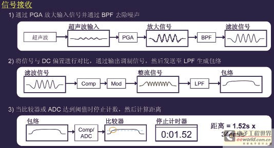
Figure 3 Ultrasonic signal reception
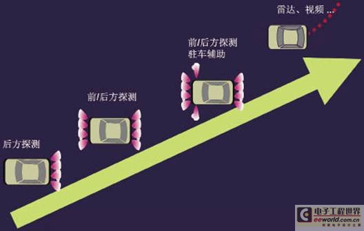
Figure 4 Development trend of reversing radar
Figure 4 shows the development trend of reversing radar. As can be seen from the figure, the initial reversing radar only has rear detection. The current reversing radar not only realizes front and rear detection, but also can detect both the left and right sides. There are some more advanced technologies already used in high-end cars.
Low-end reversing radar system
The reversing radar system generally consists of two parts, namely the probe part and the main control part. The probe part is generally installed at the rear or both sides of the car, while the main control part is located at the front of the car, close to the car driver. The probe part of the low-end reversing radar (Figure 5) usually contains only ultrasonic sensors, while the main control part includes the CPU and all peripheral circuits. The probe and the main control board are connected by a conductive line to transmit the sending and echo signals. One main control board has 3 to 4 probes. Low-end reversing radar systems usually have lower costs. They often use discrete components and have low integration, which results in poor performance. The effective measurement distance is less than 1.5m. In addition, the alarm also uses a simple buzzer.

Figure 5 Block diagram of low-end reversing radar system
Mid-range parking radar system
In addition to installing ultrasonic sensors on the probe, the mid-range reversing radar system also includes amplifying and driving circuits for the transmitted signal and amplifying and signal conditioning circuits for the received signal, which can reduce the influence of noise introduced by the signal in long-term transmission. In addition, on the control board, two-stage amplification and band-pass filters are used to improve the measurement performance. The measured distance is usually displayed by digital display, and is accompanied by a sound alarm and prompt.
High-end reversing radar system
Figure 7 is a system block diagram of a high-end reversing radar system. It can be seen that some of the functional modules that were originally on the main control end have been transferred to the probe end. It is characterized by a signal amplification circuit and a processor on the probe. The measurement signal is processed on the sensor, so there is no long-term transmission of the existing signal. Interference problems. In addition, it can calibrate each sensor individually and communicate with the main CPU through LIN or other serial methods. Because the volume of the probe part is usually relatively small, in order to achieve signal amplification and processing on the probe, a higher integration device is needed to facilitate the integration of the sensor and the PCB board.
Figure 8 shows the requirements for the coverage area of ​​the reversing radar sensor. It requires a minimum of 100 ° in the range of 70 ± 5cm in the horizontal direction; a minimum of 40 ° in the range of 100 ± 5cm. In the vertical direction, the minimum is 60 ° within the range of 50 ± 5cm; the minimum is 20 ° within the range of 110 ± 5cm.

Figure 6 Block diagram of the mid-range reversing radar system

Figure 7 Block diagram of high-end reversing radar system

Figure 8 Requirements for the coverage area of ​​reversing radar sensors
Cypress reversing radar control system reference design
The main reasons for Cypress's reversing radar control system to use the PSoC system are: 1. Its resources are flexible, PSoC's module resources are programmable, and can be reconfigured for product needs of different customers and different positioning; 2. High integration and integration It has PWM w / DB, comparator, A / D converter PGA and other analog modules, which has a high degree of analog integration; 3. It requires almost no external devices, reducing BOM cost and circuit board size; 4. Its IP It has strong protection ability and is difficult to be copied.
The PSoC reversing radar controller uses the CY8C24633 chip as the main control chip. The chip uses M8C processor, running speed up to 24M, contains 8 × 8 multiplier and 32-bit accumulator. The working voltage range is 3V ~ 5.25V, and the temperature range is industrial grade: -40 ℃ ~ 85 ℃. The PSoC chip includes 4 digital modules and 4 analog modules (2CT / 2SC). In addition, it has a high-speed 8-bit SAR AD converter optimized for motor control.
Figure 9 is the hardware block diagram of the Cypress reversing radar system, using CY8C24633 for the main control board. This design uses a sensor that integrates transceivers and adds a primary amplifier circuit to the sensor. The driving signal is a pulse signal of 40 kHz. Each sensor is connected to the main control board with a 3-wire connection, and it can connect up to 6 sensor inputs. Raise the AC signal level to better handle the echo signal. The internal analog module can be configured as a PGA, comparator, and band-pass filter, and interconnected within the device. The main control board and the display are connected through a serial port, and the display displays the detection distance in a digital manner.
Figure 10 shows the configuration of PSoC internal modules and signal routing. As you can see from the figure, the four digital modules are configured as PWM timers, timers, and serial port generators, respectively. The four analog modules are configured as two PGA amplifiers and a band-pass filter, and the signal routing can also be clearly seen from the figure.

Figure 9 Cypress reversing radar control system hardware block diagram
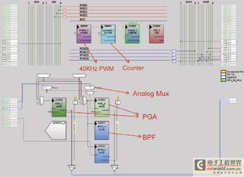
Figure 10 PSoC internal module configuration
Home Heater means for heating equipment. The heater can be divided into several types due to the different of heating principle, heating channels, thermal conductivity media and scope. Our factory produce and sale Gas Heater, electric heater, Kerosene Heater. The heater is easy to remove and heating, are widely used in homes and public places. Our gas heater use imported heat-resistant fire net, net life more than 10years; The heater use pure copper valve core, pure copper gas tube, pure copper spay nozzle, durable and no leakage; Our heater have dual heating function with flame control lever, heater and cooker 2 in 1; The heater use steel body, all steel thickness more than 0.6mm, sturdy and durable; The heater`s piezoelectric ignition switch, life can be over 30000 times.
1. imported heat-resistant fire net, net life more than 10years.
2. pure copper valve core, pure copper gas tube,pure copper spay nozzle, durable and no leakage, longer life more than 10 years.
3. dual heating function with flame control lever, heater and cooker 2 in 1, whole unit life more than 10 years.
4. moderately dry your room, purifying the environment, effectively inhibit the growth of bacteria.
5. steel body, all steel thickness more than 0.6mm, sturdy and durable.
6. exquisite outline, easy handhold design, portable anywhere at your disposal.
7. steel surface treatment by ECO electroplating technique to avoid steel rust.
8. piezoelectric ignition switch, life can be over 30000 times.
9. fire or gas can be turned up and down freely.
10. unbreakable, shock-resistant, sturdy, durable package to ensure product transit safety.
Home Heater
Home Heater, Electric Home Heaters, Portable Home Heaters, Home Gas Heaters
Ningbo APG Machine(appliance)Co.,Ltd , http://www.apgelectrical.com