introduction
This article refers to the address: http://
In most countries, taxis are a very common and convenient means of transportation. Most developed countries have built a perfect taxi dispatching system to achieve efficient taxi operation. For example, in the United States, 98% of the taxi operations and telephone reservations are handled, and “road throwing†accounts for only 2%; in London, Cities in developed countries such as Paris and Singapore, unless they make an appointment by phone or at a designated stop, rarely see passengers taking taxis on the streets, which greatly improves the efficiency of public transportation resources. However, in most cities in China, passengers are still mainly on the streets. Although some cities have already implemented GPS installations in taxis and recorded taxi location information in real time, they do not make good use of these GPS location information for taxis. The dispatch service has caused many taxi GPS systems to become furnishings. In order to further improve the operational efficiency of China's taxi dispatching system and improve the practicality of GPS system, it is necessary to study a fast and efficient taxi dispatching system combined with GPS/GIS technology.
This paper designs and implements a new type of taxi dispatching system. This system improves the current dispatching system's calling mode and proposes a grid-based taxi dispatching algorithm. The algorithm combines the taxi GPS location information uploaded by the communication platform. GIS system grid information groups taxis to achieve efficient coordination and scheduling of taxis within and between groups, which greatly improves the scheduling efficiency of taxis.
1 system design
The system consists of three parts: taxi dispatch terminal, communication platform and dispatch center. The dispatching terminal is an intelligent embedded device based on Samsung S3C2440 hardware platform and WINCE operating system, which realizes communication and on-site intelligent control with the dispatching platform; the dispatching terminal realizes the collection, reporting and scheduling information display of GPS data; the communication platform provides accurate, Efficient information transmission function; dispatch center realizes rapid taxi scheduling and real-time monitoring function of vehicles based on GIS.
1.1 Taxi dispatch terminal design
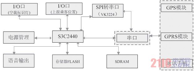
The taxi dispatch terminal includes two parts on the hardware: a system board based on Samsung S3C2440 and a device expansion board based on VK3224. The system board and the expansion board communicate through the SPI interface. The system board includes:
S3C2440 ARM9 core processor, memory FLASH, SDRAM, power management device, RS232, I/O port no-load indicator light interface and report passenger information button. The interface board includes: VK3224, GPS module, GPRS module and RS232. The dispatch terminal is designed to add a button for the taxi driver to report the passenger position. The function of each taxi driver on the road can report the passenger position information found on the road. The empty taxi came to the service.
The hardware structure of the terminal is shown in Figure 1.
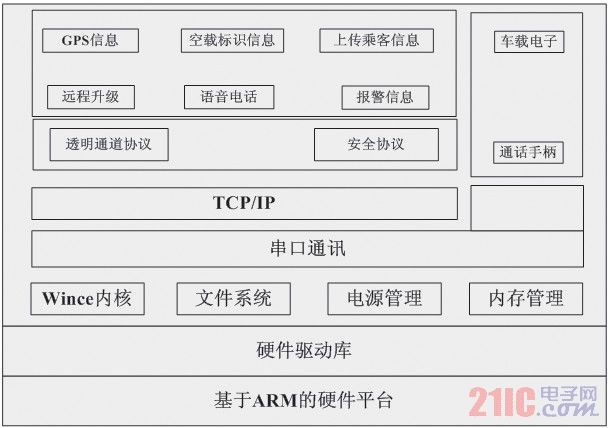
The taxi dispatch terminal uses a transparent channel in the software design to provide a reliable data transmission layer. The transparent channel communicates with the server through the TCP/IP protocol encapsulated in the GPRS. When the master station controls a serial port device on the terminal, the serial port data is loaded into the data packet sent by the primary station, and after the data packet is transmitted to the terminal, the terminal will The serial port data is directly sent to the corresponding serial port device. When the serial port device returns data, the system loads the data on the TCP/IP data packet and sends it to the primary station through GPRS. In the application layer of the primary station, there is no direct operation serial port. the difference. The GPS location information is uploaded between the dispatching terminal and the server, the passenger information is reported, and the dispatching instruction is sent through a transparent channel. Schematic diagram of the scheduling terminal software is shown in Figure 2.
1.2 Communication platform
In order to realize the communication between the platform and the taxi and collect the passengers' calling information, the communication platform includes three modules: the M2M communication module, the short message platform and the call center.
(1) The M2M communication module realizes the communication function of the taxi and dispatch center, including: taxi location upload, roadside passenger location upload, dispatch center command delivery, and the like. The M2M communication module uses TCP/IP technology based on the GPRS network, and the server side adopts the Windows platform completion port (IOCP) technology, thereby ensuring that a single server can simultaneously access a large number of taxi dispatch terminals (more than 5000 units). The biggest advantage of the completion port is the processing efficiency when managing massive connections. The high efficiency of I/O processing is achieved through the relevant mechanism of the operating system kernel. Because of the huge amount of connections in the taxi scheduling process, and the packets sent and received on each connection. Smaller, usually only a few k or even less than 1k bytes, so it is suitable to use the completion port technology.
(2) The SMS platform and the call center module implement communication between the passenger and the dispatch center. The main functions are passenger location and taxi request collection. The short message platform is responsible for receiving the short message scheduled by the short message, and then the dispatching center analyzes the short message content and completes the short message scheduling. The call center is responsible for the telephone link, and the operator and the system use the dispatch center module to implement telephone scheduling based on the incoming call content.
1.3 Dispatch Center Design
The dispatch center is divided into a foreground application and a background service program.
The foreground application software adopts the B/S architecture, which mainly includes three parts: system management, registration management and scheduling management.
(1) System management includes: department management, user management, role management, and authority management;
(2) Registration management includes: fixed telephone registration and mobile phone registration. The fixed telephone registration completes the association binding between the fixed telephone and the single fixed calling position, such as a hotel, a company, etc., records the latitude and longitude information of the location through the GIS system; the mobile phone short message registration completes the binding of the mobile phone number and several fixed calling positions, Each binding has a tag short message instead, and the latitude and longitude information of each car location in the GIS system is recorded.
(3) Scheduling management includes: driver mutual assistance scheduling, operator scheduling, registered telephone scheduling, SMS scheduling and other modules.
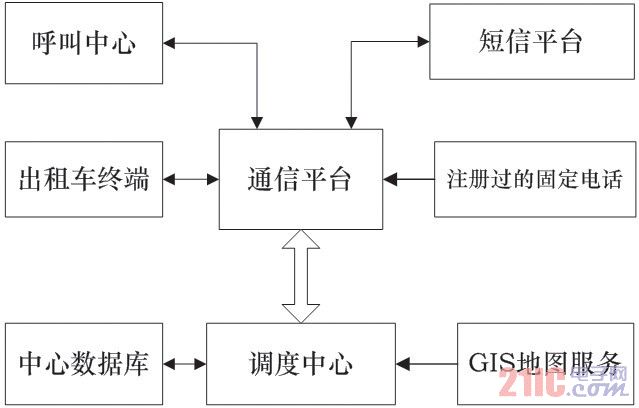
The background service program uses the C/S architecture to link the taxi GPS location information collected by the communication platform with the passenger GPS location information, and completes the comprehensive scheduling, scheduling platform and communication platform through the grid-based scheduling algorithm described in the next section. Is a close contact module, the specific relationship is shown in Figure 3.
Figure 3 Scheduling system overall architecture (see right column)
2 system key module design
2.1 Calling design
There are two types of taxi modes in the existing taxi dispatching system at home and abroad: one is that the passenger calls to report his position, the dispatcher or the attendant signs the passenger position on the GIS map; the other is that the passenger triggers the TAXI site to call the button. car.
The system adds and improves the calling mode based on the original mode.
1) Add a report passenger position button on the dispatch terminal. When the taxi is full on the road, if it encounters a passenger on the roadside, this button is triggered to realize the real-time reporting of the passenger position by the taxi driver. This method reflects a kind of The idea of ​​"I am for everyone, everyone is for me", this kind of mutual assistance and collaboration, has expanded the space for searching passengers.
2) Register the driving location in advance in the GIS map, and bind the latitude and longitude information of the location to the fixed telephone number. The passenger dials the dispatching center with the bound fixed telephone, and the dispatching center can determine the calling location of the dialing user. Telephone scheduling. In this way, the registered fixed telephones (including: home fixed telephone and public telephone booth telephone, etc.) are equivalent to the taxi calling station. This kind of calling mode, the dispatching center does not need manual participation, and the system automatically completes the scheduling.
3) SMS calls the car, the passengers register a few places where they often take a taxi, such as home, company, etc., then associate the location's latitude and longitude information, mobile phone number and location tag, passengers need to send a pre-registered location when calling the car Label SMS, the dispatching center can determine the location of the calling passenger, thus realizing SMS scheduling. These three modes of calling, the dispatching center does not require manual intervention by the dispatcher, and automatically dispatches to facilitate passengers and save resources.
2.2 Grid-based scheduling algorithm
Most of the existing taxi dispatching centers are designed as manual service modes. First, the dispatching center continuously collects the status of the taxis registered in the system, and then sends the taxis in the idle state to a queue according to the first-in-first-out principle; For each online reservation passenger request, the dispatcher will manually determine the most convenient one according to his past experience. If there are multiple taxis at the same time to satisfy the request, the dispatcher will go to the service according to the advanced first service. Mode labor costs are high and service quality is difficult to improve.
The system abandons the manual service mode and adopts the system automatic scheduling mode.
The dispatching service program uses a grid-based taxi scheduling algorithm. The specific process of the algorithm is as follows:
(1) Divide the city grid. According to the size of the city on the GIS map, the city is covered with an appropriate rectangular frame to obtain the latitude and longitude information of the diagonal of the rectangular frame: the latitude and longitude values ​​of the upper left corner are (a, b), and the latitude and longitude values ​​of the lower right corner are (c, d); The number of city taxis determines the number of grids (M x N).
The total number of city taxis is Tsum, the taxi idling rate is Pec, and the number of empty taxis is Tec=Pec×Tsum. The number of selected grids is approximately equal to the number of empty taxis Tec≈M×N. For the convenience of calculation, generally M and N are selected as powers of 2 (eg, 16, 32, 64, 128, ...), and at the same time The length and width are as close as possible, so choose the M/N ratio as close as possible.  value.
(2) Divide the urban latitude and longitude array. After determining the M and N values, the selected city longitude range (a, c) is divided into M shares and stored in the longitude array citylongitude[M], and the adjacent value interval is  At the same time, the urban latitude range (b, d) is divided into N shares, stored in the latitude array citylatitude[N] , the adjacent value interval is
  . The latitude and longitude array is divided into the following grid for calculating the taxi and requesting passengers using the dichotomy.
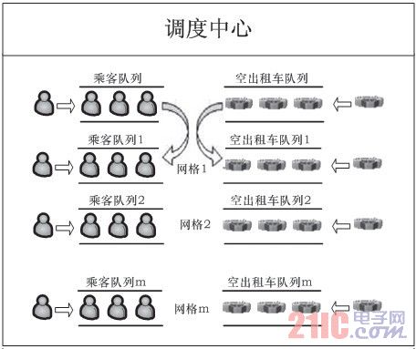
(3) Grid information maintenance. The grid array CityGrid[M][N] is determined by dividing the urban latitude and longitude array. The grid data structure includes basic information such as grid latitude and longitude, and each grid dynamically maintains two linked lists: grid empty car list and grid passenger list . The urban grid structure is shown in Figure 4.
a. Grid empty car list initialization. According to the location, all the empty taxis in the current system are calculated by the binary method to load the grid of the taxi into the corresponding grid empty car list, because the grid empty car list needs to be based on the status information reported by the taxi terminal. Real-time adjustment, the addition and deletion of the linked list is more frequent, so the grid empty car list in this system uses a double-linked list structure. The node data structure in the linked list is shown in Table 1.
Table 1 Taxi data structure

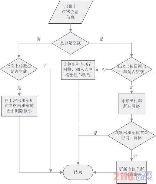
b. Grid empty car list dynamic maintenance. According to the status information reported by the taxi terminal in real time, it is judged whether it is in the no-load state. If it is no-load, it is judged whether the taxi in the linked list is in an empty state. If it is no-load, it is determined whether the taxi needs to be adjusted to the grid. If the taxi is not in the linked list, the grid is calculated according to the reported GPS location information, and the taxi is inserted into the grid empty car list, and the no-load state is calculated. If the reporting status is full, it is determined whether the taxi is in the idle state. If it is empty, it is deleted from the empty train list, and the full load status is calculated. The specific processing flow chart is shown in Figure 5.
The unscheduled passengers calculate the grid to which the passenger belongs according to the location, load it into the corresponding grid passenger list, and follow the “first request first serviceâ€.
In principle, the grid passenger list in the system adopts a linked list queue structure, and the node data structure in the linked list is as shown in Table 2.
Table 2 Passenger data structure

(4) Passengers request dispatch. By step (3), the taxi and the passenger are grouped according to the grid. If the grid passenger list is not empty in a single grid, select a passenger from the linked list, and judge whether the grid hollow list is empty, if not Empty, select an empty car from the linked list to satisfy the passenger request; if the grid hollow car list is empty, select the empty car in the adjacent grid hollow car list to satisfy the passenger request until the empty car is searched. After searching for the empty taxi, the passenger GPS position and the passenger's specific text description position are sent to the taxi terminal. After the transmission is successful, the passenger is deleted from the grid passenger list, and the corresponding empty car is taken from the grid empty car list. delete. At this point, the scheduling process is complete.
3 Simulation and performance testing
We use a server (DELLR710 rack server, XEON E5504×2JSDM/4G memory stick) as the dispatching server, simulate the city grid divided into 64×64=4096 system scheduling, and one PC simulates 10000 taxi data. Upload GPS location and status information, upload interval is 10s, test content includes: taxi driver mutual assistance scheduling, telephone scheduling, SMS scheduling. Through the simulation test 10,000 taxis running, the dispatch server CPU usage rate is 49%, which proves that the system is efficient and feasible.
4 Conclusion
This paper designs and implements a new type of taxi dispatching system based on GPS/GIS. The system improves the existing taxi dispatching terminal and the calling mode, and proposes a grid-based taxi dispatching algorithm to realize automatic taxi. Scheduling minimizes human participation, and the simulation proves that the algorithm is efficient and practical. Through the system, the passenger waiting time (CWT) and the taxi emptying rate (ECP) can be effectively reduced, and the operating efficiency of the taxi system can be improved.
12V Wall Charger is one of the normal wall plug Adapter, the output is 12V, and the normal dc plug size are 5.5*2.5mm, and 5.5*2.1mm etc . And Yidahsun can produce different plugs for choose like: EU plug, US plug, UK plug, Australia plug, Argentina plug and Brazil plug, which used in different countries.
12V wall power adapters are popularly used for LED light, LCD monitor and CCTV camera etc. Customers should buy right plug wall adapter.
Yidashun's 12V wall plug adapter is with smart IC to protect your devise with over current protection, over load protection, short circuit protection, over heat protection!


12V Wall Charger
12V Wall Charger,Acer Tablet Charger,Lenovo Tablet Charger,12V Portable Wall Charger
Shenzhen Yidashun Technology Co., Ltd. , https://www.ydsadapter.com