Abstract: The purpose of car door lock control is to design a control circuit specially designed to prevent the driver from forgetting the key in the car. It is mainly composed of a combination of each switch input signal and a basic gate circuit commonly used in several digital circuits. The essence of this design is the integrated application of combinatorial logic gates in automotive digital circuits. This paper analyzes the working process of the door lock control circuit under various conditions, and uses the learned digital gate circuit knowledge to design the car door lock control circuit.
Keywords: car door lock control; digital circuit design; unlock; lock
With the rapid development of automotive electronic control technology, the degree of automotive automation control is getting higher and higher. Various electronic circuits and micro-processing technologies play an important role in the control of automobiles, such as EFI control of engine oil quantity and stepless control of automatic transmission gears. Especially in high-end cars, automatic cruise driving, car speed control door lock mechanism, etc. can also be realized. Among these many functions, the central control door lock control is an important content.
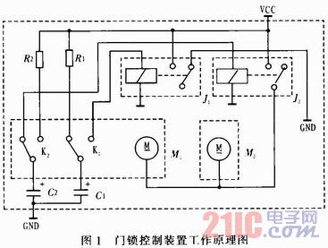
1 Features of the car door lock control circuit Modern cars are equipped with door lock devices, which are generally unlocked and locked. When locked, the door cannot be opened by the inner and outer handles. The working principle diagram of the traditional car door lock circuit is shown in Figure 1. When the car key is rotated or the door handle is pressed, the lock mechanism will be driven to drive the state switch K1 and K2 to operate, and the capacitor C1 (or C2) is discharged. The relay J1 (or J2) Suction and energization of the motor M1 (or M2) to drive the locking mechanism. After the power is discharged, the relay is released, the motor is stopped, and the unlocking process is automatically completed.
This article refers to the address: http://
If the driver forgets to pull the key during this process, pressing the door handle to lock the door will leave the car key in the key hole of the ignition switch, causing great trouble. Therefore, in order to avoid the above situation, the door lock control circuit is specially designed. The feature of this design is that when the driver forgets the key in the ignition switch, the driver will be provided with a signal that the door is unlocked, so that the driver checks whether the key is not pulled out; When the door is ready to lock the car, if the door is not closed, the driver will be provided with an unlocking signal to remind the driver to inspect the door to prevent the door from being completely locked, so as to avoid unnecessary personal and property. loss.
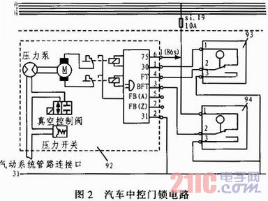
With the car's requirements for passenger comfort, ease of handling, and safety of use, today's cars use electronically controlled door lock systems as shown in Figure 2, using electronic technology and radio technology, and some are also connected. The car's central microcomputer control system is connected to the start-up and ignition system for anti-theft control. The car door lock control circuit in this design mainly refers to the digital circuit design part, that is, the electronic control unit at 92 in Fig. 2.
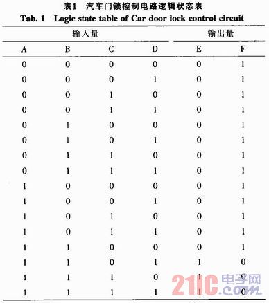
2 Car door lock control circuit analysis According to the control requirements of the car door lock control circuit, under normal circumstances, when the driver pulls out the engine key and prepares to lock the car, the key position detection switch state is 1; then the door state detection is performed. When the four doors are closed, the door status detection switch is also 1, and the unlock signal can be issued and the output is 0, and the lock signal is determined by the state of the door lock or the door lock control switch. When one of the switches is in the locked state, a lock signal is issued and the output is 1.
When the key is forgotten in the ignition switch, that is, the key position detection switch state is 0, the unlock signal is issued and the output is 1, and the lock signal output is 0, that is, the door cannot be locked, that is, the driver is reminded that the key is forgotten in the vehicle.
When the door is not closed, that is, if one of the four doors is not closed, the door status detection switch is 0, the unlock signal is issued and the output is 1, and the lock signal output is 0, so that the door cannot be locked, reminding The driver's door is not closed.
The following is based on the general steps of the combination logic circuit design method in the digital circuit to analyze the vehicle door lock control circuit.
2.1 Logic abstraction 1) Determine the input and output variables, and perform the logic state assignment input variable according to the control requirements: key position detection switch A, define 1 when the key is pulled out from the ignition switch, 0 when inserted; door state detection switch B, it is 1 when the door is closed, 0 when the door is open; the door lock state detection switch C is 1 when the lock is defined, 0 when the lock is unlocked; the door lock state is detected as D, and the lock is 1 when the lock is locked. The time is 0. The output variable is: lock state detection terminal E, the output is locked when the output is 1, the unlocked state when the output is 0; the unlock state detection terminal F, the door is unlocked when the output is 1, and the output is 0. Unlocked state.
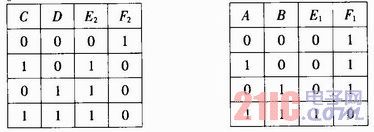
2) List the logic status table (ie truth table) according to the control requirements
For the convenience of analysis, the A and B variables in the input are taken as a group, the corresponding output variables are E1 and F1; the C and D variables in the input are taken as a group, and the corresponding output variables are E2 and F2; The relationship between E1, E2 and E, and the relationship between F1, F2 and F.
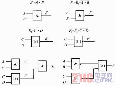
2.2 According to the truth table, the logic function relation and its corresponding logic circuit diagram are obtained by further analysis: E=E1·E2; F=F1+F2
Then get the complete logic circuit diagram as:
3 Automotive door lock control circuit design and experimental simulation
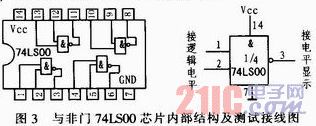
3.1 Chip Introduction According to the analysis of the car door lock control circuit, the control circuit should be realized by using NAND gates or NOR gate chips (AND and OR gates can be replaced by NAND gates and NOR gates). The following is a brief introduction to these chips.
1) Two input 4 output NAND gate 74LS00 chip
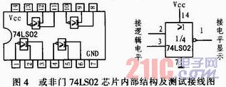
2) Two-input 4-output or non-gate 74LS02 chip
3.2 Experimental Simulation According to the logic circuit diagram and the chip wiring diagram, the circuit is connected, and the various inputs of the vehicle door lock control are simulated, and the correctness, rationality and scientificity of the design are tested. The simulation results are shown in Table 1.
4 Conclusions The analysis and design of the vehicle door lock control circuit are described in detail, and it is verified that the control circuit is successful under laboratory conditions. The circuit features simple principle, compact structure, small size, low power consumption, low cost, and can be installed on various types of automobiles. Through design, it is more proficient in the use of basic logic gate circuits, can be more familiar with the design steps of combinatorial logic circuits, and has a more detailed understanding of the car door lock control circuit, and is designed for the deeper control requirements of automotive door lock circuits in the future. A good foundation is laid down to better improve the reliability and stability of the system.
The unique acicular radiator,360 degree dissipation small wind resistance. High heat dissipation efficiency ensuring that the LED chip can work for 50000 hours.
Color temperature 3000-6000K
Light≥90LM/W
Matching the 2.3.4 lane,tunnel and Landscape Lamp,floodlight dedicated lens.Ensure that intensity and uniformity.
Glare index Signification reduce the original LED Module size,removal of power supply problems.Low demands for application situation and installation personnel More suitable for the transformation of traditional lamps.

Technical parameters
Power :30W,30W,15W,15W
Structure size: 135×100×40 mm, 208×74×49 mm, 125×58×30mm, 380×40×25mm
Lens size: 135×100 mm, 186×64 mm, 125×58mm, 355×40mm
Input voltage: 220 V, 220 V ,220 V, 220 V
Input current: 0.132 A, 0.132 A ,0.123 A, 0.125 A
Luminous flux: 2760 LM ,2400 LM ,1230 LM ,1300 LM
Light effect: 92 LM/W 80 LM/W 82 LM/W 86 LM/W
Color temperature: 5000 K 5000 K 5000 K 5000 K
Power factor: 0.99 PF 0.98 PF 0.98 PF 0.99 PF
Working temperature: -40+50°C, -40+50°C, -40+50°C ,-40+50°C
Led Module,Led Modules For Signs,Led Module Bulb,Led Modules For Signage
Jiangsu chengxu Electric Group Co., Ltd , https://www.satislighting.com