**Phase Compensation of the Op-Amp**
In order for an operational amplifier (op-amp) to function properly and maintain stability, a phase compensation capacitor is often added between the input and output in the circuit. This is especially important when dealing with feedback networks that can introduce phase shifts, potentially leading to instability or oscillation.
**1. About the Compensation Capacitor**
While there are theoretical calculations involved in determining the appropriate value for the compensation capacitor, many engineers rely on practical experience rather than complex equations. The choice of capacitance should consider the system's frequency response. In general, a larger capacitor will reduce the bandwidth and may lead to oscillation if not carefully chosen. If a calculation is necessary, it’s useful to look at the input parasitic capacitance of the op-amp. For example, in a negative feedback amplifier, the product of the feedback resistor and the desired capacitance plays a key role in determining the system’s stability.
**2. Two Main Roles of the Compensation Capacitor**
1. **Adjusting Phase Shift:** The capacitor helps to adjust the phase shift introduced by the feedback network, compensating for the inherent phase lag of the op-amp itself.
2. **Compensating for Input Capacitance:** It also helps to counteract the effects of the input capacitance of the op-amp, which can cause instability at high frequencies.
Since real-world op-amps are not ideal, they introduce phase shifts at certain frequencies. When this signal is fed back into the input, it can cause the amplifier to become unstable or even oscillate. To prevent this, a compensation capacitor is typically built into the op-amp. However, additional capacitors can be added externally depending on the application and frequency requirements.
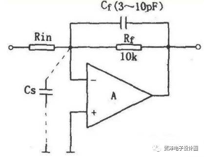
The input parasitic capacitance (Cs) of a linear amplifier, particularly one using negative feedback, can significantly affect circuit stability. This capacitance, which includes both the op-amp’s input capacitance and wiring-related distributed capacitance, forms a lag network with the feedback resistor (Rf). At high frequencies, this causes the output voltage to lag in phase. The upper cutoff frequency (Ωh) of the amplifier is approximately:
$$
\Omega_h = \frac{1}{2\pi R_f C_s}
$$
If Rf is large, the upper frequency limit is reduced, and the phase lag from Cs and Rf could lead to unwanted oscillations. A simple solution is to lower Rf to increase Ωh beyond the operating frequency range. However, this reduces the gain of the amplifier, since the voltage gain (Av) is given by $ Av = -R_f / R_{in} $. To maintain a high gain, a more common approach is to add a compensation capacitor (Cf) in parallel with Rf. This creates a phase lead network that counteracts the phase lag caused by Cs. Since Cs is usually unknown, perfect compensation is difficult, so variable capacitors are often used to fine-tune the phase shift experimentally. Typical values for Cf are 3–10 pF when Rf is around 10 kΩ. For a voltage follower configuration, a slightly larger Cp might be used.
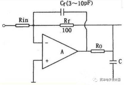
When the output load capacitance (CL) is significantly larger than 100 pF, the combination of the output capacitance (including parasitic capacitance) and the op-amp’s output resistance can introduce additional phase shifts. These can accumulate and cause parasitic oscillations, leading to serious instability. One solution is to place a small resistor (Ro) in series with the op-amp’s output to isolate the load capacitance. The feedback resistor (Rf) is then connected after Ro. This setup helps to reduce DC attenuation and maintains proper feedback. A capacitor (Cf) is often added to further stabilize the system. The value of Cf should be chosen such that its reactance at the unity-gain frequency (fT) is less than 10% of Rf. Typically, Ro ranges from 50 to 200 Ω, and Cf is about 3–10 pF.
Other sources of instability may come from the internal characteristics of the IC or from the power supply coupling in the system. In some cases, multiple methods may be needed to solve the problem. However, a well-chosen compensation method—such as overcompensation by increasing the internal compensation capacitor—can significantly improve stability. For example, increasing the compensation capacitor by a factor of 9 or more has been shown to work well for certain op-amps like the μA301.
Dm Filter Inductor,Cylindrical Power Inductor,Ring Inductor Filter,Custom Common Mode Inductive Filters
Huizhou Show-Grand Electronics Co., Ltd. , https://www.sgtransformer.com