Introduction
Now MEMS microphones are gradually replacing electret condenser microphones (ECM) in audio circuits. The functions of the two microphones, ECM and MEMS, are the same, but the connection between each and the rest of the system is different. This application note will introduce these differences and provide design details based on a simple MEMS microphone-based replacement circuit.
ECM connection of audio circuits
ECM has two signal leads: output and ground. The microphone is biased by the DC bias on the output pin. This bias is usually provided by a bias resistor, and the signal between the microphone output and the preamp input will be AC ​​coupled.
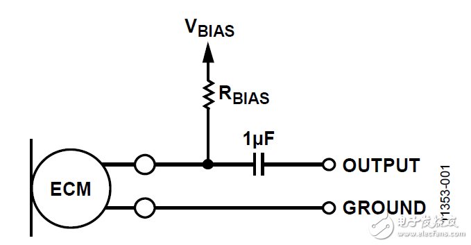
Figure 1. ECM circuit connection
A common use case for ECM is as an inline voice microphone in a headset connected to a mobile phone. In this case, the connector between the headset and the phone has four pins: left audio output, right audio output, microphone signal, and ground. In this design, the output signal of the ECM and the DC bias voltage are transmitted in the same signal line. The bias voltage source is usually about 2.2 V.
MEMS microphone difference
No input bias voltage is used on the signal pins of analog MEMS microphones. However, it is a three-terminal device with different pins for power, ground, and output. The supply voltage of the VDD pin is generally 1.8 to 3.3 V. The signal output of the MEMS microphone is biased by the DC voltage, which is generally equal to or close to 0.8 V. In design, the output signal will usually be AC ​​coupled.
Compared to ECM, the key advantage of using MEMS microphones is its stronger power supply rejection (PSR) performance. The PSR of a MEMS microphone is usually at least 70 dBV, but ECM has no power supply suppression capability at all, because the bias voltage is directly connected to the microphone through a resistor.
Circuit changes required to replace ECM with MEMS microphone
For a system originally designed around ECM, the basic challenge when switching to a MEMS microphone is that there is no separate signal for the power supply and microphone output, such as when using a headset microphone. If you make some small changes to the circuit, you can use MEMS microphones in such designs. First, the downstream signal provided by the DC offset in the signal chain must be isolated from the microphone output signal. Secondly, the DC bias must be used to power the MEMS microphone, and the output signal of the microphone must not be allowed to interfere with the power supply. DC bias isolation can be achieved through AC coupling capacitors, and MEMS microphone power can be provided through a carefully designed circuit that acts as a voltage divider and low-pass filter. The following design uses the ADMP504 MEMS microphone as an example. A 2.2 k bias resistor is used.

Figure 2. MEMS microphone using a wire for power and output signals
Figure 2 shows a design example that implements the above functions. In the earphone design, the circuit part on the left side of the earphone connector will be in the actual earphone, and the 2.2 k bias resistor and 1 F AC coupling capacitor will be in the source device (such as a smartphone). Resistors R1 and R bias form a voltage divider, and the MEMS microphone reduces the V bias voltage to the supply voltage of the VDD pin. Depending on the values ​​of V bias, R bias, and the required VDD voltage, resistor R1 may need to be very small, as shown in the following example. To calculate the required series resistance (R bias + R1), the microphone can be modeled as a resistor through which a fixed current will flow. At VDD = 1.8 V, the typical supply current of the ADMP504 is 180 A. According to Ohm's law, when the voltage on VDD is 1.8 V, the microphone can be modeled as a 10 k resistor. To solve for the appropriate value of resistor R1, the voltage divider formula used is:
[Microphone VDD] = [Bias Voltage] & TImes; (10 k / (10 k + R1 + R bias))
According to this formula, a 2.2 k R bias resistor and a 499 R1 resistor will divide 1.73 V from the 2.2 V bias voltage to the microphone VDD. When choosing the value of R1, trade-offs need to be made; as shown below, this value is too large will cause VDD to be too small, but in order to prevent C2 from being too large, this value cannot be made too small.
	Hikvision's Miniature Dash Cams are compact, high-quality devices designed for vehicle safety.
They provide clear, crisp video footage in both daylight and low-light conditions, ensuring reliable evidence in case of road incidents.


	With features like wide-angle lens, automatic recording, and G-sensor for emergency recording, these dash cams capture every detail on the road.Easy to install and user-friendly, they're perfect for enhancing driver safety and accountability.
mini driving recorder ,mini dash cam front and rear,mini dash camera for car,Miniature dash cams,dashcam mini,miniature dash cams
Hangzhou Hikauto Technology Co.,Ltd , https://www.hikmotorstore.com