Due to the popularity of electronic products, devices that can be powered by a variety of power sources are not uncommon. For example, industrial handheld meters or portable medical diagnostic devices are battery-powered most of the time, but once plugged into an AC adapter or USB port, power is drawn from the AC adapter or USB port, both for charging the battery and for powering the system. At the other end of the mobile system, there are at least two power supplies in the large high availability server rack to keep the server up and running in the event of any power failure. The storage server uses a supercapacitor as a backup power source to cleanly and error-freely shut down when the main power supply is disconnected. Of course, some servers use a large current main power supply and a small current auxiliary power supply. All of these systems face an important task, choosing one of the various available power supplies to power the system load.
Hidden problems in power multiplexing
The task of choosing the right power source for a given environment sounds simple and easy, but if you choose it improperly, the consequences are serious and can cause system failure and damage to the power supply. If the voltage applied to the output of the power supply is high, switching between power supplies operating in parallel may cause current to flow back into the power supply. Some power supplies will fail if they encounter energy return, causing the control loop to be interrupted, causing overvoltage at the power input terminals, which may cause capacitors and other devices to burn out. There is also a risk in parallel power switching, that is, the disconnection time between all power supplies and outputs may be too long, resulting in a drop in output voltage, system reset or system operation is not normal. The third problem arises when the voltages between the power supplies are relatively close. Some comparator-based control methods introduce an oscillating mode that continuously switches between power supplies, so that switching between power supplies requires careful design.
Same power supply
Let's start with the simplest case—powering one system from two identical power supplies. The same meaning here is the same nominal voltage, which is typically a few percent of the power supply tolerance. This happens in high-availability servers that are equipped with two or more redundant power supplies to run uninterrupted in the event of any power failure. In such systems, a simple method is to select the power supply with the highest voltage to power the system. The anodes of the two diodes are connected to two power supplies, and the cathodes are connected together to form a so-called diode OR circuit, thus achieving the function of supplying power from a higher voltage source (see Figure 1). This circuit works normally when only one power supply is connected. In the presence of two power supplies, the higher voltage supply has its diode forward biased and the other diode reverse biased.
Figure 1: The diode OR circuit of two power supplies supplies power to the load.
There are multiple boards in the new server, and the power can easily exceed kW, so the 12V DC power supply must supply 50A ~ 100A. Using ordinary old-fashioned diodes, even for Schottky diodes with low dropout voltages, diode "or" for such two 12V supplies, if not impossible, faces terrible thermal management tasks because at such high currents When the voltage of the two diodes drops by 1V, it consumes a lot of power. For example, at 50A, the power consumption is 50W. Therefore, an ideal diode with a much lower voltage drop is required. Just as many other circuit problems have been solved, the MOSFET has once again extended its help. The MOSFET is coupled to a sense circuit that acts as an ideal diode. When forward biased (input above output), the turn-on voltage difference is very low, and when reverse biased (input below output) is turned off. The ideal diode drop can be reduced to 1/10 of a typical diode, so the power consumption is reduced to 5W. Such an ideal diode OR circuit is easily realized by a single or parallel N-channel MOSFET with an RDS (ON) of 2 m. Figure 2 shows one such circuit and its IV curve. Linear Technology's LTC4352 controls an N-channel MOSFET for ideal diode functionality. Such two circuits are connected in parallel to form an ideal diode OR circuit that can be used in a redundant power system. Linearly following the voltage drop of the MOSFET in a certain ratio ensures that the power supply does not oscillate and smoothly switches, while the fast turn-on and turn-off time of 0.5μs minimizes the output voltage drop and reverse current.
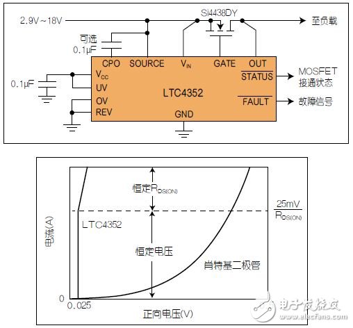
Figure 2: LTC4352 ideal diode with UV/OV and its IV curve.
The function of an ideal diode is beyond the reach of passive diodes. The LTC4352 becomes an ideal diode only when the input is within the effective range of the undervoltage (UV) and overvoltage (OV) threshold settings. The STATUS# pin provides a status signal for the MOSFET to be turned on or off to the downstream circuit, and the FAULT# pin indicates whether the MOSFET is turned off due to UV/OV conditions, or is the MOSFET being resistive or open, causing excessive voltage drop. An alarm is issued that is about to fail before the failure occurs.
Medium Rate Nicd Battery KPM Series
Established in 1956, during the China first five-year-plan, Henan Xintaihang Power Source Co., Ltd. (Factory No.755) was the first R&D and manufacturing enterprise in China in the field of alkaline storage batteries and modular power system and it was also the military factory which owned the most varieties rechargeable batteries in domestic. Taihang was located in national Chemistry and Physicals Power Source Industrial Park, Xinxiang City, Henan, China.
Medium Dishcharge Rate Nickel Cadmium Battery, KPM10~KPM1000, 0.5C ≤Max. discharge current <3.5C
The nickel–cadmium battery (NiCd battery or NiCad battery) is a type of rechargeable battery using nickel oxide hydroxide and metallic cadmium as electrodes. The abbreviation NiCd is derived from the chemical symbols of nickel (Ni) and cadmium (Cd).
Ni Cd Rechargeable Battery,Kpm500Ah Battery,Medium Discharge Rate Nickel Battery,Nickel Cadmium Battery For Ups
Henan Xintaihang Power Source Co.,Ltd , https://www.taihangbattery.com