1 Introduction
Wind energy and solar energy are two kinds of renewable energy sources, but their time and geographical distribution are different. Therefore, pure wind energy street lamps and photovoltaic street lamps are not compatible with the reliability of wind-solar complementary street lamps. The wind-solar complementary street lamp is an independent power supply system that effectively utilizes the complementary energy and time characteristics between wind energy and solar energy, and simultaneously supplies the battery to each other through the respective power generating devices to provide an independent power supply for the street lamp. Therefore, the wind-solar hybrid power generation system is cost-effective and suitable for independent power systems.
Lead-acid batteries play an important role as energy storage modules in off-grid wind-solar hybrid power generation systems. The battery pack accounts for a large proportion of the initial investment (about 20%), and the cost of the battery is about 90% in the later maintenance cost, which is also one of the weakest links in the whole system. Practical experience shows that if the battery can avoid working in overcharge and over discharge for a long period of time, its service life will be extended by 3 to 5 times. Therefore, a battery charge control system with low cost and intelligent power management is studied. Realistic meaning.
2 The composition and working principle of the wind and solar complementary street light system
The system of wind and solar complementary street lamps is mainly composed of a solar battery module, a breeze wind power generator, a battery pack, a lamp holder, a rectifier, a controller, and a light source. The working principle of the system is: under the control of the intelligent controller, the solar cell module charges the battery pack during the day, and the breeze wind generator can charge the battery pack as long as the wind speed reaches the starting wind speed, and the night breeze wind generator and the battery pack provide Power to the high-pressure sodium lamp, because the controller has a power-dissipation function, so that it can ensure that the battery pack is not damaged by overcharging or over-discharging under any conditions (windy, windless, sunny or long-term rainy days) [ 1]. Its composition principle is shown in Figure 1 [1]:

Figure 1 Schematic diagram of the wind and solar complementary street light system
3 Model classification
Figure 2 shows a model commonly used in batteries. The model is also called the Thevenin equivalent circuit of the battery, including the equivalent capacitor C, the equivalent resistance R between the parallel plates, the voltage source Us, and the battery internal resistance Rs. It is assumed that these parameters are constant values ​​and therefore an approximate model of a battery. And assume that the technical parameters of a set of lighting systems are shown in Table 1.
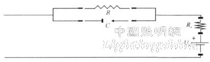
Figure 2 Battery equivalent circuit diagram
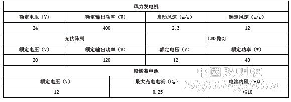
Table 1 Technical parameters of wind-solar complementary LED street light system
4 Battery charging and discharging method and control research
4.1 Theoretical basis of battery charging
In the mid-1960s, American scientist Mass made a lot of experimental research on the charging process of open batteries, and proposed a charging curve acceptable to the battery with the minimum outgas rate, as shown in Figure 3. It can be seen from the best curve that a large charging current is used in the initial stage of charging to speed up the charging speed, and the charging current is reduced at the end of charging to prevent the gas from being excessively severe to cause the active material on the electrode plate to fall off and damage, thereby reducing the battery capacity and life.
4.2 General charging method
4.2.1 Constant current charging method
The constant current charging method is a charging method in which the output voltage of the charging device is adjusted or the resistance in series with the battery is changed, and the charging current intensity is kept constant, as shown in FIG. 2 . The control method is simple, but since the acceptable current capability of the battery is gradually decreased as the charging process progresses, the charging current is mostly used to electrolyze water and generate gas to make the gas out too late. Therefore, the stage charging method is often used.
4.2.2 Stage Charging Method
1) Two-stage charging method. First charge with a constant current to a predetermined voltage value, and then change to a constant voltage to complete the remaining charge, as shown in Figure 5 (a). Generally, the conversion voltage between the two phases is the constant voltage of the second phase.
2) Three-stage charging method. As shown in Fig. 5(b), constant current charging is used at the beginning and end of charging, and charging is performed with a constant voltage in the middle. When the current decays to a predetermined value, the second phase is switched to the third phase. This method minimizes the amount of gas output, but is limited as a fast charging method.
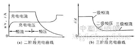
Figure 5 stage charging curve
4.2.3 Constant voltage charging method
This charging method seldom electrolyzes water and avoids overcharging of the battery. However, in the initial stage of charging, the current is too large, which has a great influence on the battery life, and it is easy to bend the battery plate and cause the battery to be scrapped.
5 Battery Control Modeling
5.1 Double closed loop PID design
As shown in Figure 6 [2, 3], this control mode can be used to achieve constant voltage current limiting charging of the battery. Due to the current closed-loop control, this limit value is the current reference value Ig for constant current charging. The battery voltage is used as the external loop feedback amount, and Vg is used as the charging voltage reference value. Inside the dotted line is the current control loop. There is a limiter outside the box to limit the charging current.

Figure 6 block diagram of constant voltage current limiting charging control circuit
5.2 Current closed loop design
As shown in Fig. 7 [2, 3], it is a dynamic analysis structure diagram of the current loop. (Ig)s is a given current and (Id)s is a charging current.

Figure 7 Current loop dynamic analysis structure
The transfer function of the thyristor rectifier can be regarded as the inertia link. Since the current measurement circuit has hysteresis, the transfer function can be approximated as a small inertia loop. For the sake of simplicity, this control link can be regarded as a simple proportional link, the proportional coefficient is K1, and the parameters of the current regulator are:

Where, (WACR)s is the transfer function of the current regulator PI; S is the Lagrangian operator; Ki is the steady state gain, and Ti is the time constant. K1=Ig(max)/Id(max), Ks=1, Ti=T, then the current loop open-loop transfer function is:
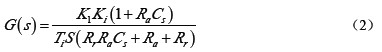
In the formula, (Ig)max and (Id)max are the maximum values ​​of Ig and Id, respectively; Ra is the internal resistance of the battery; Cs is the filter capacitor; and Rr is the internal resistance of the rectifier. Since Ra and Rr are extremely small, take  , the current loop open loop transfer function can be simplified to:

The current loop closed-loop transfer function is:

Equation (4) shows that the current loop can be designed according to a typical I-type system. Its parameter KjTj=0.5, Tj is the current loop inertia time, and when Tj=30ms, Kj is 16.7.
5.3 Voltage closed loop design
The closed-loop transfer function of the current loop is known by equation (4). The proportional coefficient is K2=Ug(max)/Ud(max), and the voltage regulator parameters are:

Where Ug(max) and Ud(max) are respectively given voltage and charging voltage maximum; Kv is the steady state gain of the voltage regulator; Tv is the time constant of the voltage regulator.
Then the open loop transfer function of the voltage loop is:
Its closed-loop transfer function is:

It is known from equation (7) that the cutoff frequency of the current loop is low, with reference to a typical type I system design. Take KjTv=0.5, Tv==180ms, then Kv=36.
6 Simulation results and conclusions
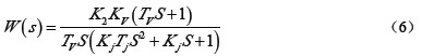
As shown in Fig. 8, after the parameter is set, the simulation results are obtained according to the simulation model. Among them, Fig. 8(a) and (b) adopt the constant voltage charging mode, the tracking speed is fast, the usage time is less than 0.3s, no static difference, no Overshoot, Figure 8(c) reduces the limiter amplitude Ig to 1A and tests the current limit charging mode. The results show that the current loop can effectively limit the magnitude of the charging current, making it smaller than the limiter amplitude.
The simulation results show that: (1) The double-closed loop PID control can realize the constant voltage current limiting charging mode. (2) The two-stage charging method of the lead-acid battery after constant current and constant voltage is simple, stable and feasible, and can also be applied to other distributed power generation systems.
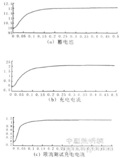
Figure 8 Simulation results
3-5HP Compressor Series Sealed Terminal Blocks
The 3-5 HP Compressor Series Sealed Terminal Blocks product is a hermetic terminal block for 3-5 HP compressors. They are waterproof, dustproof and shockproof for stable operation in harsh environments. These blocks are manufactured from high-quality materials to ensure durability and reliability. This series of products is available in a variety of sizes and dimensions to suit different models of compressors. They are easy to install and use for efficient connection of power and control lines. 3-5 HP Compressor Series Sealed Terminal Blocks are an important part of the compressor industry and are used in a wide range of industrial and commercial applications.
3-5Hp Compressor Series Sealed Terminal Blocks,Conditioning Compressor Three-Phase Terminal,Dc Air Conditioner Compressor,Air Conditioner Compressor Connector With Rubber
Shenzhen Capitol Micro-Electronics Co.,LTD , https://www.capitolgtms.com