challenge
At present, the control strategies based on the motor model at home and abroad still have many problems in the low speed pulsation, high speed field weakening, stability and output torque consistency of the motor. In order to better solve the problem of low-speed torque ripple of the motor, this paper establishes a motor model that introduces the dead time of the inverter. The dead time of the inverter is very short and the switching process of the IGBT still has the problem of delay and lag. In order to accurately capture the distortion of the voltage waveform caused by the dead time, the data acquisition card is required to have a high sampling rate. In addition, in order to make the research result more accurate, the board needs to have a higher signal to noise ratio and is effective. Bit. In summary, in the study of voltage waveform distortion caused by dead time, a board with high sampling rate, high precision and high signal-to-noise ratio is needed to meet the requirements of signal acquisition.
solution
Firstly, the dead zone effect is analyzed. A simulation method is proposed to reduce the distortion of the voltage waveform caused by the dead time. By applying the data with 16-bit high-resolution A/D converter and synchronous sampling rate up to 16MS/s. The acquisition card PCI-9846H cooperates with the current sensor, voltage sensor, torque meter, motor and its controller, dynamometer and other equipment to complete the construction of the vehicle motor test platform, and carries out the host computer data through the LABVIEW related driver provided by ADLINK. The development and design of the acquisition system, through the collection and analysis of voltage, current, torque and speed information, the method proposed in this paper to reduce the distortion of the output voltage waveform is verified. The test results are based on the data of PCI-9846H. The acquisition system has high sampling rate and high sampling precision, which can meet the requirements of signal waveform distortion caused by dead time in this paper. At the same time, the improved method proposed in this paper can improve the output waveform of voltage and reduce the dead zone. The effect of time on the performance of the motor at low speeds
introduction
The motor drive system is the core part of the electric car [1-2]. According to the type of motor used, it can be divided into DC motor drive system and AC motor drive system [3]. In AC motor drive system, induction motor is easy to accept and widely used. Permanent magnet synchronous motor has its own high energy density. With high efficiency, it has a relatively large competitive advantage and its application range is increasing.
In order to meet the dynamic performance requirements of the vehicle, the motor drive system must have high dynamic performance. The current successful control strategies include: variable frequency variable pressure control (VVVF) based on steady state model and field oriented control (FOC) based on dynamic model. And Direct Torque Control (DTC). Among them, direct torque control is developed on the basis of vector control. Its main advantages are: the decoupling idea in vector control is abandoned, the flux linkage and torque of the motor are directly controlled, and the vector is replaced by the stator flux linkage. The orientation of the rotor flux linkage in the control avoids the identification of parameters (rotor resistance, etc.) that are difficult to determine in the motor. At present, the mathematical model of the permanent magnet synchronous motor at home and abroad is based on the introduction of the rotor flux linkage, the stator leakage reactance, and the mutual inductance of the windings under the condition that the neutral line does not take out the three-phase symmetrical winding, ignoring the bearing and other stray losses. And the influence of factors such as PWM wave on the motor, so the control strategy based on the motor model has many problems in the low speed pulsation, high speed field weakening, stability and output torque consistency of the motor [5]. In order to better solve the problem of low-speed torque ripple of the motor under direct torque control, this paper establishes a motor model that introduces the dead time of the inverter. By analyzing the generation and action mechanism of the dead time, it is concluded that The key influence factors of output voltage waveform distortion and phase change, a method to reduce the distortion of voltage waveform caused by dead time is proposed for the simulation results. By applying PCI-9846H, current sensor, voltage sensor, torque meter, motor and its control The equipment, dynamometer and other equipment complete the construction of the vehicle motor test platform. The host computer writes the data acquisition system through LABVIEW. Through the collection and analysis of voltage, current, torque and speed information, the proposed dead time is reduced. The method of distortion of the output voltage waveform was verified.
1. Research on inverter dead time
1.1 Inverter dead time generation mechanism
For permanent magnet synchronous motor drive, when the IGBT is working normally, the upper and lower arms are alternately complementary. During the alternation process, there must be a state in which the upper and lower arms are simultaneously closed, ensuring that the corresponding complementary lower/upper arm is reliably shut off before the upper/lower bridge arms are turned on, and the time when the upper and lower arms are simultaneously turned off is called For the dead time. According to the investigation of IGBT on the market, the dead time of the inverter is generally 3~7μs [6]. When the motor works above a certain speed, since the fundamental voltage is large enough, the dead zone effect has little effect on the fundamental voltage, so it is not taken seriously; but when the motor works at low speed, the fundamental voltage is small, and the dead zone effect The influence on the fundamental voltage is relatively large. The longer the dead time, the greater the loss of the output voltage of the inverter, and the distortion of the voltage waveform will also become larger. In addition, the dead time will affect the phase of the output voltage. The PWM waveform is no longer symmetrical to the center, resulting in increased motor losses, reduced efficiency, and output torque ripple. Figure 1 shows the mechanism of dead time generation and the effect on the output voltage, where V is the ideal PWM voltage output waveform and Ua- is the negative bus.
Voltage, Ua+ is the positive bus voltage, v is the error voltage, and Ia is the output current.
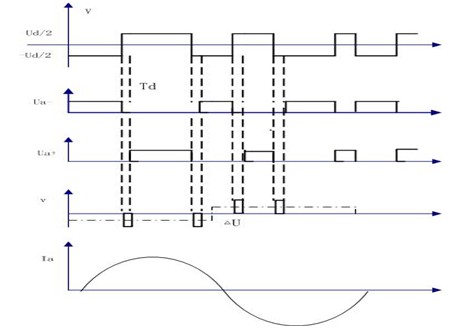
Figure 1 Dead zone effect
As shown in Figure 1, it can be found that the error voltage has the following characteristics [7]:
1) There is an error voltage pulse during each switching cycle;
2) The amplitude of each error voltage pulse is Ud;
3) The width of each error voltage pulse is Td;
4) The polarity of the error voltage pulse is opposite to the polarity of the current;
Although an error voltage pulse does not cause too much change in the output voltage, the distortion of the voltage waveform caused by the total error voltage in one cycle is more serious. The following is an analysis of the influence of the error voltage on the output voltage waveform in a half cycle. .
1.2 Analysis of output voltage waveform distortion caused by dead time
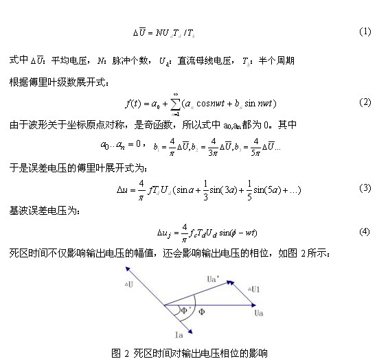
Using the concept of average voltage [8], assuming that the carrier frequency is very high and does not contain zero crossings in one carrier cycle, the average of the error voltage pulse trains in a half cycle is:
MC Air series Showcase LED Display is mainly used in clothes chain store, Shopping mall, Library, Supermarket and so on. Product categories of LED Display For Fixed, Indoor Showcase led display and Outdoor Showcase led display. We have R & D and manufacturing team and the perfect after-sales service and technical support for wholesale high quality showcase Led Display,.
Showcase led display is highly customized regards to pixel pitches, resolution, sizes, shapes etc. Our showcase led display walls enjoys long life span, they are weatherproof units and can tolerate dust, humidity or rain.
For Outdoor Showcase led display, it is viewable in direct sunlight. The picture quality is not compromised in our solution, hence the display is crystal clear despite it`s day time.
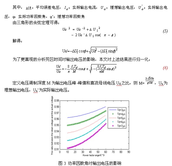
Showcase LED Display
Showcase LED Display,Transparent LED Screen,LED Display Signs,Showcase LED Advertising Display
Shenzhen Macion Optoelectronics Technology Co.,Ltd. , https://www.macion-led.com