0 Preface
In the application of video detection, medical imaging and infrared image fast tracking system, more and more complex two-dimensional, three-dimensional or even four-dimensional image processing requires a parallel processing system and can run complex algorithms. To achieve these complex systems, high-end FPGA + high-performance DSP is currently widely adopted, and the performance of a single DSP has reached its limit, so to solve complex parallel algorithms, multi-core DSP is a new direction of development, including the root of multi-core DSP Loading technology is one of its difficulties.
TI's DSP chip TMS320C6678 (C6678) has a high-performance DSP with 8 cores, each operating at 1 GHz.
The supported boot modes are SPI, I2C, EMAC, SRIO, and parallel port Emif16 NOR-FLASH. Among them, the Emif16 NOR-FLASH mode is a kind of system that does not need to be participated by the host computer and is relatively simple and independent. Most independent DSP systems adopt this mode.
Online search for some of the C6472 and C6678 sporadic loading data, all with the help of third-party conversion tools, too general. The following is a detailed discussion on the power-on loading of the parallel port Emif16NOR-FLASH of C6678.
1 C6678 power-on loading process
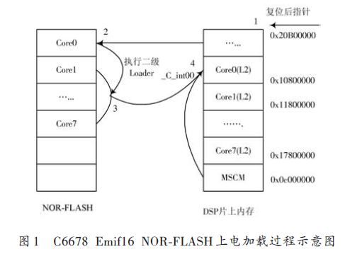
The so-called power-on load (power-on bootstrapping) is a small program that runs before the DSP program is reset and runs normally before the user program, just like the BIOS of a PC. Multi-core loading is very different from single-core loading, not only for the loading of the main core but also for the loading and activation of other cores. The C6678's Emif16 NOR-FLASH can directly execute the program (XIP) (this is different from the C641x series DSP), and its power-on loading process is shown in Figure 1.
After power-on reset, the DSP first runs the program that is solidified on the on-chip ROM at address 0x20b00000, called the on-chip Loader. The on-chip Loader determines the Boot mode used by the user to jump to the corresponding mode of the secondary loader according to the DSP hardware pin state. In the Emif16 NOR-FLASH mode of Figure 1, after running the on-chip Loader, the PC pointer directly points to the NOR-FLASH first address 0&TImes; 70000000 and starts to execute the second-level Loader program on the FLASH. The second-level Loader is stored in the FLASH start address 0&TImes; ~0&TImes; within the range of 70000400. The root table data of the application (that is, the data of the application written to the FLASH) is saved from 0×70000400. The function of the second-level Loader is to move the root table data of Core0~Core7 stored in the FLASH to the corresponding address segment of the DSP. After the move, the PC pointer of the second-level Loader program jumps to the main program entry address _c_int00 of Core0. Start executing the Core0 application. The application at Core0 starts with code that makes other cores active (this is also different from the single core), and the entire multicore load is now complete. In fact, if your application is small and the running speed is not high, the 2, 3, and 4 processes in Figure 1 can be omitted. Just write the original code data of the application to FLASH starting from 0×70000000. Location, power-on normal operation (this is not possible on the C641x), so many high-performance DSPs can not be reflected, and most of the multi-core projects use embedded sysbios project, occupying a large memory, so the normal boot process must The secondary loading process shown in Figure 1 is employed.
As seen in Figure 1, a complete multi-core loading process, the developer needs to do is the preparation of the secondary loader Loader, the generation of the image file in FLASH, the writing of the FLASH writer, the main verification of the trigger code of each auxiliary core. Written (the loaded application is not in this scope).
We engineer Loudspeaker solutions that offer great durability, quality sound, and peak performance. When an electrical signal is applied to the voice coil it generates a magnetic field. The voice coil and magnets within the Speaker interact causing the coil and attached cone to move, generating sound. Our loudspeakers incorporate large magnets and particular voice coils to handle a broad range of frequencies and sounds. Additionally, our loudspeakers can be configured in multiple cone materials, sizes, shapes and gaskets to adapt to different operational environments. We have provided loudspeaker solutions for both indoor and outdoor applications. Our loudspeaker designs can be found in home theater systems and on the handlebars of some of the most exquisite motorcycles.
Loudspeaker
Lond Speaker,Lead Wire Speaker,Waterproof Loudspeaker,Micro Waterproof Speaker
Jiangsu Huawha Electronices Co.,Ltd , https://www.hnbuzzer.com