**1. Introduction**
With the rapid development of the economy, the number of vehicles on the road has significantly increased, leading to growing pressure on urban traffic systems. Traffic congestion and accidents have become common issues, especially during peak hours. To address these problems, many cities have introduced zebra crossing traffic lights to manage the interaction between pedestrians and vehicles. However, traditional systems often fail to adapt to real-time changes in traffic conditions, resulting in inefficiencies. This paper presents an intelligent zebra crossing traffic light system that dynamically adjusts its timing based on pedestrian density and vehicle flow. By incorporating
Sensors and microcontroller technology, the system improves traffic management and enhances safety for both drivers and pedestrians.
**2. Overall System Design**
The traffic light system is designed to display red and green signals for pedestrians, as well as red, yellow, and green signals for vehicles, along with corresponding time durations. The pedestrian signal’s red light duration is equal to the combined green and yellow times of the vehicle signal. Conversely, the pedestrian green light duration matches the vehicle’s red light duration. The system continuously monitors traffic volume and pedestrian count using pressure sensors or counters to adjust the two-way signal timings in real time. During high-traffic periods, when a certain threshold of pedestrians is reached, the crossing time is extended, while during low-traffic periods, it is shortened. The system consists of four main modules: control and expansion, detection and conversion, reset and crystal, and display. A block diagram of the system is shown in Figure 1.
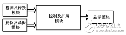
The control and expansion module handles system operations, the detection and conversion module collects and processes data from sensors, the reset and crystal module ensures stable timing, and the display module provides visual feedback to users.
**3. Hardware Design**
**3.1 Control and Expansion Module**
The system uses the MCS-51 series microcontroller 8051 as the core. It offers cost-effectiveness, ease of development, and strong bit processing capabilities. The 8051’s internal timer is used to generate accurate time intervals by combining hardware and software. A 6MHz clock frequency is selected to balance performance and power consumption. The expansion module allows for additional I/O ports to be added, ensuring flexibility in system design.
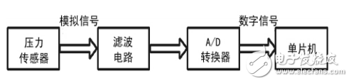
**3.2 Detection and Conversion Module**
This module employs a PTH501 pressure sensor to detect pedestrian and vehicle presence. The sensor converts weight into an electrical signal, which is then amplified, filtered, and converted into digital data for the microcontroller. The system compares this data with preset thresholds to adjust signal timings accordingly.
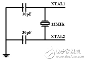
**3.3 Reset and Crystal Module**
The reset circuit ensures the microcontroller starts from a known state, while the crystal oscillator provides a stable clock signal. A 12MHz crystal is used to maintain precise timing for the system’s operations.
**3.4 Display Module**
The system uses LED digital tubes for displaying time and status. These are energy-efficient, durable, and easy to read, making them ideal for real-time traffic signaling.
**4. Software Part**
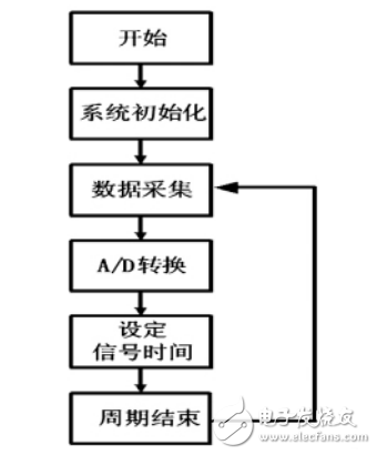
The software plays a crucial role in controlling the system. Upon startup, the microcontroller collects and processes data from pressure sensors, compares it with predefined values, and adjusts signal timings accordingly. The main program flow is illustrated in Figure 4.
**5. Conclusion**
This intelligent zebra crossing traffic light system, built around the 8051 microcontroller, effectively adapts to changing traffic conditions. It offers reliable performance, easy maintenance, and scalability. Its ability to respond in real time makes it a promising solution for improving urban traffic safety and efficiency.
AS-i Passive Distributor
The AS-I (i.e. actuator-sensor interface) bus belongs to the bus system at the bottom device level. It is a two-wire network for digital input and output, which complies with EN50295 and IEC62026-2 specifications.
Various types of digital devices can be connected, such as: sensors, limit switches, buttons, valves, relays, light curtains and emergency stop switches, etc., and send signals to higher-level controls such as PC, PLC, CNC or DCS system. In general, AS-I does not require shielded cables and terminal resistors.
The unshielded two-wire cable used carries both the signal and the power. Generally speaking, the AS-I bus system is simple and reliable, easy to install and fast to configure, and is widely used in industrial automation fields such as logistics, automobile production, petrochemical industry, and elevator control.
The As-I Passive Distributor simple module is pierced and connected to the flat cable, which is suitable for installation in a narrow space, and can provide connection methods such as aviation connectors.
As-I Passive Distributor,As Interface Distributor,Distributor With Pur Cable,Custom As-I Passive Distributor
Kunshan SVL Electric Co.,Ltd , https://www.svlelectric.com