**1. Introduction**
With the rapid development of the economy, the number of vehicles on the road has significantly increased, leading to greater pressure on urban traffic systems. As a result, traffic congestion and accidents have become more frequent. To address this issue, many cities have implemented zebra crossing traffic lights to manage the interaction between pedestrians and vehicles. However, traditional systems often fail to account for real-time variations in traffic conditions, making them less effective in adapting to changing demands. This paper presents an intelligent zebra crossing traffic light system that dynamically adjusts signal timing based on pedestrian flow and vehicle density, offering a more efficient and responsive solution to urban traffic challenges.
**2. Overall System Design**
The intelligent traffic light system is designed to display red and green signals for pedestrians, along with countdown times, while vehicles are shown red, green, and yellow signals with corresponding time displays. The duration of the pedestrian red light is set equal to the combined green and yellow time of the vehicle signal. Meanwhile, the pedestrian green time matches the vehicle's red light duration. The system continuously adjusts the transit time based on real-time traffic volume and the number of pedestrians waiting to cross. During peak hours, when the pedestrian count reaches a certain threshold, the crossing time can be extended, while during off-peak hours, it is reduced accordingly. Pedestrian detection is achieved using either a counter or a pressure sensor, with the latter being preferred for accuracy.
The system consists of four main modules: 1) the control and expansion module, 2) the detection and conversion module, 3) the reset and crystal oscillator module, and 4) the display module. A block diagram of the system is illustrated in Figure 1.
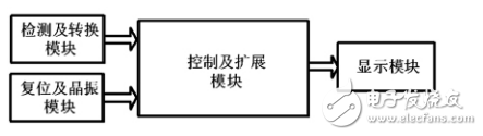
*Figure 1: Overall block diagram of the system*
The control and expansion module manages the overall system operations, while the detection and conversion module measures traffic flow and pedestrian numbers using pressure Sensors, converting the data into digital signals for processing by the microcontroller. The reset and crystal module ensures stable system operation by generating the necessary clock frequency and resetting the circuit when needed. Finally, the display module shows the current signal timings for both pedestrians and vehicles.
**3. Hardware Design**
**3.1 Control and Expansion Module**
The system uses the MCS-51 series 8051 microcontroller as its core control unit. It offers low cost, ease of development, and strong bit manipulation capabilities, along with a full-duplex serial communication port. Timing functions are implemented using a combination of hardware counters and software delays. After dividing the MCU’s clock frequency by 12, the system sets up a 50ms timer (T0), which triggers an interrupt every 50ms. A software counter with an initial value of 20 is used to track seconds, allowing the system to update the display accurately. The 8051 operates at a clock frequency of 6MHz, chosen to balance performance and power consumption.
For I/O expansion, the system utilizes the P1 and P3 ports, as other ports may be reserved for external memory or peripheral devices.
**3.2 Detection and Conversion Module**
This module employs a pressure sensor to measure the number of pedestrians and vehicles. The sensor converts the detected load into an electrical signal, which is then amplified, filtered, and converted into a digital signal via an ADC. The microcontroller compares the input values with preset thresholds to adjust the signal timings. The PTH501 pressure sensor is suitable for this application, with a range of 0–150 MPa and an accuracy of ±0.2% FS. Its fast response time of 5ms makes it ideal for real-time monitoring.
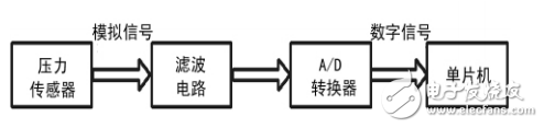
*Figure 2: Block diagram of the detection and conversion module*
**3.3 Reset and Crystal Module**
**(1) Reset Module**
The reset function initializes the microcontroller, setting the program counter (PC) to 0000H so that the CPU starts executing from the beginning. The system includes automatic power-on reset to ensure reliable startup, with a minimum reset pulse duration of two clock cycles.
**(2) Crystal Module**
The 8051 microcontroller includes an internal oscillator that, when paired with an external crystal, provides the necessary clock signal. A 12MHz crystal is used in this design, connected to the XTAL1 and XTAL2 pins. Capacitors C1 and C2 are typically 30pF for crystals and 47pF for ceramic resonators.
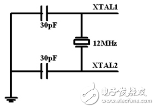
*Figure 3: Clock circuit diagram*
**3.4 Display Module**
The system uses an 8-segment common cathode LED display for time indication. LEDs are chosen for their efficiency, durability, and clarity. The display is driven dynamically, reducing the number of required interfaces and improving system simplicity.
**4. Software Part**
The software is the core of the system, responsible for collecting and processing data from the pressure sensors. It compares the input values with predefined thresholds to determine the appropriate signal timing. The main program flow is shown in Figure 4.
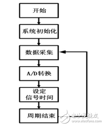
*Figure 4: Main program flow chart*
**5. Summary**
The proposed intelligent zebra crossing traffic light system is built around the 8051 microcontroller and uses pressure sensors to monitor traffic conditions in real time. By adjusting signal timings dynamically, the system improves traffic flow and safety. It is highly adaptable, easy to maintain, and offers reliable performance with a short development cycle. This design represents a practical and efficient solution for modern urban traffic management.
SVLEC offers a variety of cables designed to support industrial protocols including AS-I, Can Open, Device Net, Ethernet/IP, Ether CAT, Profibus, Profinet . Based on customers' request , the cable length can be any meter .


Field Bus,M12 A-Code Connector,M12 Profibus Cable,Custom Devicenet Connection Cable
Kunshan SVL Electric Co.,Ltd , https://www.svlelectric.com