Induction cookers use the principle of electromagnetic induction to heat food. The furnace surface of the induction cooker is a heat-resistant ceramic plate. The alternating current generates a magnetic field through the coil below the ceramic plate. When the magnetic field lines in the magnetic field pass through the bottom of the iron pot or the stainless steel pot, eddy current is generated, and the bottom of the pot is rapidly heated to reach the food. purpose.
This article refers to the address: http://
The heating principle of the induction cooker is shown in the figure. The cooktop table is a high-strength, impact-resistant ceramic plate (crystallized glass). The high-frequency induction heating coil (ie, excitation coil), high-frequency power conversion device and corresponding control are installed under the table. The system has a flat-bottomed cooking pot on top of the countertop.
The working process is as follows: the current and voltage are converted into direct current by the rectifier, and the high frequency alternating current is converted into a high frequency alternating current exceeding the audio by the high frequency power conversion device, and the high frequency alternating current is applied to the flat hollow spiral induction heating coil, thereby generating High frequency alternating magnetic field. The magnetic lines of force penetrate the ceramic platen of the cooktop and act on the metal pan. In the cooking pot, there is a strong eddy current due to electromagnetic induction. The eddy current overcomes the internal resistance flow of the pot body to complete the conversion of electric energy to thermal energy, and the generated Joule heat is the heat source of cooking.
1 Overview
The electromagnetic cooker is an advanced electronic cooker for cooking food in modern homes by applying the principle of electromagnetic induction. It is very convenient to use and can be used for cooking, frying, frying, steaming, frying and other cooking operations. Features: high efficiency, small size, light weight, low noise, energy saving, no pollution, safe and hygienic, uniform heating during cooking, can better maintain the color, aroma, taste and nutrients of food, is not to modernize the kitchen The new type of electronic cookware that is missing. The power of the induction cooker is generally around 700-1800W.
The induction cooker is divided into two categories, low frequency and high frequency, according to the current frequency in the induction coil. Compared with the high frequency electromagnetic cooker, the heating efficiency is high and the power is saved.
Classified by style, you can divide the following three.
Desktop Induction Cooker: It is divided into single head and double head. It has the advantages of convenient placement and strong mobility. Because the price is lower and more popular.
Buried induction cooker: put the whole induction cooker into the cabinet surface, and then dig a hole in the countertop to make the cooktop and the countertop face a plane. Industry experts believe that this installation method only seeks aesthetics, but it is not scientific. A large part of the consumer group regards the induction cooker as a hot pot, and it is not convenient to bury the cooking.
Embedded induction cooker: can adapt to the needs of different pots, no longer have special requirements for the pot.
This article mainly introduces the use of SPMC65P2404 chip to achieve the design of induction cooker. SPMC65P2404 is an industrial control 8-bit single-chip microcomputer introduced by Sunplus. It has high cost performance and strong anti-interference ability, and is very suitable for industrial control and home appliance design. The induction cooker designed with SPMC65P2404 has the following properties:
Six heating modes: hot pot, frying, stir-fry, grilling, cooking, roasting;
An automatic working mode: boiling water;
Up to 720 minutes of timed boot function;
2-hour automatic shutdown protection function;
Small object detection function, does not heat the unsuitable objects;
The system uses various protection measures such as overcurrent, overpressure and overtemperature;
The switching power supply is used to enable the system to work normally in the voltage range of 180~250V;
The system has set the fault alarm function to facilitate fault finding and overhaul;
The system contains a self-test program to facilitate production testing.
2, induction cooker design requirements
Induction cooker as a general household product, in addition to the basic heating function, its safety performance and stability can be the key to design.
The induction cooker is equipped with various protection devices, including small object detection, overheating automatic shutdown protection, overvoltage or undervoltage automatic shutdown protection, air-burning automatic stop heating protection, 2-hour power-off protection, 1~2 minutes automatic shutdown protection, and sound and light protection. Alarm display, etc.
Taken together, the induction cooker can be evaluated by the following technical characteristics:
(1) Self-protection characteristics. The output switch tube is the key component of the induction cooker. It works in high voltage and high power state. It is limited by cost and device parameters. It is impossible to have a large margin when designing. Therefore, if the power supply voltage is too high and working during the working process. When switching, an instantaneous impact, an increase in current, an excessive rise in temperature inside the machine, a move of the iron pan away from the cooktop or no load, and the switch tube may be damaged. Therefore, it should ensure that the protection devices such as overpressure, overcurrent, overtemperature and pot detection are normal;
(2) The temperature control characteristics of the bottom of the pot. The heat at the bottom of the pot is directly transmitted to the cooker plate (ceramic glass). The cooker plate is a heat conductive material, so the heat sensitive component is generally installed at the bottom of the cooktop to detect the temperature at the bottom of the pan;
(3) Power stability. The induction cooker should have an automatic output power adjustment function to improve power supply adaptability and load adaptability;
(4) Electromagnetic compatibility. This performance involves interference with other home appliances and harm to the human body. The induction cooker is provided with an LC filter circuit in the power circuit and absorbs the leakage flux with a metal frame, and uses a pulse method to minimize the average radiation power;
Based on the performance specifications of the above induction cooker, our designed induction cooker also has the following functional specifications:
Manual control of firepower, from 300W to 1800W, is divided into 14 firepower, each gear has stable power;
Manual temperature selection, from 70 ~ 240 ° C range, a total of 6 fixed temperature selection, each file can achieve precise temperature determination;
Automatic cooking function, built-in 1 automatic cooking function: boil water.
6 kinds of optional functions: hot pot, stir-fry, steaming, stewing, frying, grilling, which can be adjusted for different firepower stalls; hot cooking, stewing, frying, grilling 4 functions can choose different temperatures.
It can realize 1~720 minutes of scheduled power-on function and 1~180 minutes of timed shutdown function.
The system provides protection for 2-hour automatic shutdown.
3, system hardware design
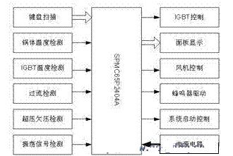
The system adopts SPMC65P2404 as the main control MCU. The main modes are: keyboard scanning, pot temperature detection, IGBT
Temperature detection, current overcurrent detection, overvoltage and undervoltage detection, oscillation signal detection, fan control, digital tube display control, LED control, buzzer control, system start control.
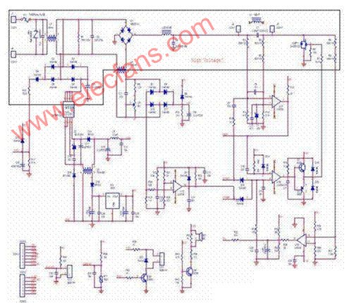
Power board circuit analysis AC 220V through the front-end filter processing, through the rectifier bridge, into a DC power of about 310v, through the MCU control IGBT turn-on and turn-off, to control the working state of the heating coil.
The switching power supply part adopts TI's latest integrated circuit VIPer12A to realize the output of different voltages. After the AC is connected, it is half-wave rectified and connected to the voltage input pin of VIPer12A. The output terminal is regulated by voltage transformer to obtain 18V and 5V DC power supply for ICs and other peripheral components.
The circuit includes a current detecting portion. The current of the total circuit is reduced by a current transformer, and then converted into a direct current by a rectification to connect a resistor to the ground. The system determines the current of the loop by checking the voltage of the resistor terminal. At the same time, if the loop current exceeds a certain value, the protection signal at the other end is fed back to the control terminal of the IGBT, and the control signal is pulled low, so that the IGBT stops working and is sent to the MCU to stop the system and generate an alarm signal.
Control board circuit analysis

The main control board is mainly composed of MCU, digital tube, light-emitting diode, button and reset circuit. The digital tube adopts common anode type, the LED driving method is dynamic scanning, the button is multiplexed with SEG line, the COM port is controlled, and the SEG is read back. I/O of the data to scan the keys. The reset circuit is a low voltage reset circuit, and when the voltage is lower than 2.6V, the system generates a reset.
4, system software design
The main process adopts a time-sharing structure, and different work is performed in each different time slice. The time slice can periodically refresh and scan the dynamically scanned LEDs to facilitate program control.
Working in a round-robin manner, you can effectively use time resources. In the process, information is mainly passed to other modules by means of flags.
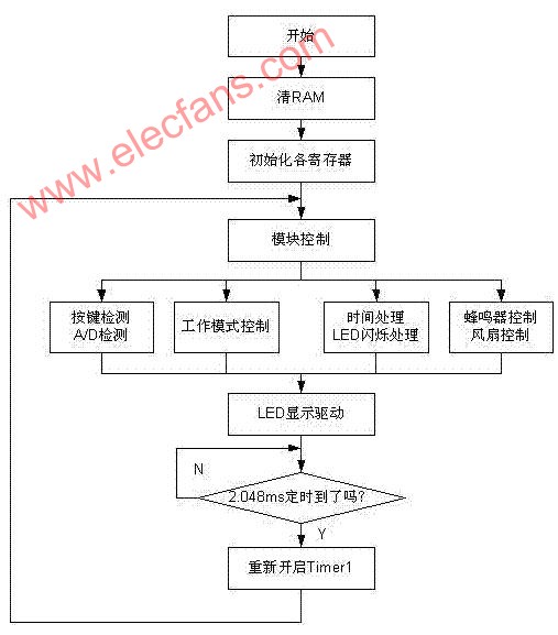
Interrupt program
The current overcurrent interrupt is the only interrupt of the whole system. When the interrupt is generated, the system immediately stops the control signal, and then sets the current overcurrent flag to let the system detect the state of the overcurrent in other places for 3 seconds. If so, the current is generated. The alarm signal of the flow stops the system.
Power conditioning module
The system needs to calculate whether the set power value has been reached according to the external voltage and current, and adjust the PWM value by comparing the power relationship to output a relatively constant power.
Assuming the external voltage is V1,
The voltage value V2 detected by the MCU is calculated according to the circuit:
V2=5.1*V1/(330+5.1)
The resulting A/D value DATA is:
DATA=V2*256/5
The relationship between the external current and the test value of the MCU through the converted voltage is:
External current value / converted voltage = 2.4
Convert the power value according to the above relationship:
P=V*I=0.06*AD(V)*AD(I)
Launch: AD(I)=100*P/(6*AD(V))
After determining AD(I), adjust the PWM value so that AD(I) reaches the calculated value.
1. Mainly is used in shipbuilding industry in the steel surface prior to paint ugh grinding; 2. The construction industry of cement concrete roadbed, steps such as horizontal flat grinding; 3. Widely used in shipbuilding, aviation, automobile, petroleum, construction and installation, etc. The product is the large metal and nonmetal materials derusting, paint, burr removal, grinding weld of high efficiency grinding tool.

Fiber Disc,Abrasive Fiber Disc,Aluminum Oxide Fiber Disc,Ao Fiber Disc
Jiangsu Loncin Electrical Equipment Co.,Ltd , https://www.loncincabletray.com