What is the role of the capacitor in the rectifier circuit? What is a half-wave rectifier circuit? Single-phase half-wave controllable rectifier circuit

How to choose the capacitor in the rectifier circuit?

Generally, the value of the capacitor satisfies R*C=(3-5)T, where R is the load resistance, which is equal to the ratio of the DC voltage of the DC output to the DC output current; C is the capacity of the filter capacitor; T is the rectification The repetition frequency of the post-pulsating DC voltage. After this selection, it is completely possible to supply power to electronic devices that do not have voltage regulation requirements. This formula is not strictly required to obey. If there is a voltage regulator circuit behind the filter, the filter capacitor takes a small point, but the voltage regulator circuit must be fully functional, and the pressure compensation at both ends is very large. It should be a relatively strong voltage regulation capability. As for the withstand voltage of the filter capacitor, for the half-wave rectification and full-wave rectification circuits, the withstand voltage of the filter capacitor is required to be larger than the maximum value of the input AC voltage of the rectifier circuit.

How does the controllable rectifier circuit control the output voltage?

The controllable rectifier circuit is usually a thyristor rectifier circuit, and its output voltage (effective value) can be controlled by adjusting its conduction angle.

What is a half-wave rectifier circuit?

Half-wave rectification circuit: Half-wave rectification is a common circuit that uses the unidirectional conduction characteristics of a diode to rectify. The rectification method of removing half a week and remaining half a cycle is called half-wave rectification. The function is to convert AC power to DC power, that is, rectification.

The working principle of the half-wave rectifier circuit:

The AC voltage of the secondary winding of the transformer is u2= U2sinωt, where U2 is

Secondary voltage rms value. The waveform of u2 is as shown:

Generally, the value of the capacitor satisfies R*C=(3-5)T, where R is the load resistance, which is equal to the ratio of the DC voltage of the DC output to the DC output current; C is the capacity of the filter capacitor; T is the rectification The repetition frequency of the post-pulsating DC voltage. After this selection, it is completely possible to supply power to electronic devices that do not have voltage regulation requirements. This formula is not strictly required to obey. If there is a voltage regulator circuit behind the filter, the filter capacitor takes a small point, but the voltage regulator circuit must be fully functional, and the pressure compensation at both ends is very large. It should be a relatively strong voltage regulation capability. As for the withstand voltage of the filter capacitor, for the half-wave rectification and full-wave rectification circuits, the withstand voltage of the filter capacitor is required to be larger than the maximum value of the input AC voltage of the rectifier circuit.

Single-phase half-wave rectification circuit: (1) Positive half cycle u2 instantaneous polarity a(+), b(-), VD is positively biased, and current flows through the diode and the load. If it is ignored to the voltage drop UF, then uo=u2. (2) Negative half cycle u2 instantaneous polarity a(-), b(+), VD

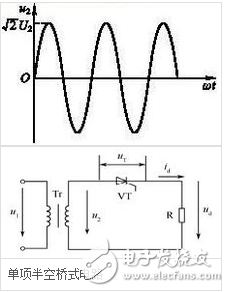
Reverse bias cutoff, IF ≈ 0, uD = u2.

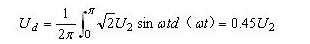
220V half-wave rectifier circuit diagram:

Generally, the value of the capacitor satisfies R*C=(3-5)T, where R is the load resistance, which is equal to the ratio of the DC voltage of the DC output to the DC output current; C is the capacity of the filter capacitor; T is the rectification The repetition frequency of the post-pulsating DC voltage. After this selection, it is completely possible to supply power to electronic devices that do not have voltage regulation requirements. This formula is not strictly required to obey. If there is a voltage regulator circuit behind the filter, the filter capacitor takes a small point, but the voltage regulator circuit must be fully functional, and the pressure compensation at both ends is very large. It should be a relatively strong voltage regulation capability. As for the withstand voltage of the filter capacitor, for the half-wave rectification and full-wave rectification circuits, the withstand voltage of the filter capacitor is required to be larger than the maximum value of the input AC voltage of the rectifier circuit.

What is a single half-wave rectifying circuit:

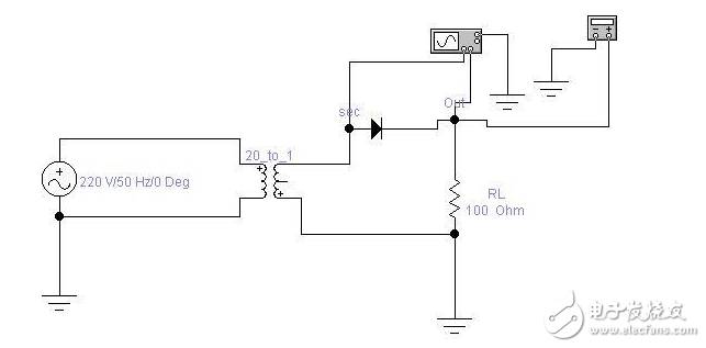
Tip: The AC side of the single-phase controlled rectifier circuit is connected to the single-phase power supply. This section describes several typical single-phase controlled rectifier circuits, including its working principle, quantitative calculation, etc., and focuses on the impact of different loads on the circuit operation.

1. Recall the single-phase half-wave uncontrollable rectifier circuit. The average output voltage is:

Generally, the value of the capacitor satisfies R*C=(3-5)T, where R is the load resistance, which is equal to the ratio of the DC voltage of the DC output to the DC output current; C is the capacity of the filter capacitor; T is the rectification The repetition frequency of the post-pulsating DC voltage. After this selection, it is completely possible to supply power to electronic devices that do not have voltage regulation requirements. This formula is not strictly required to obey. If there is a voltage regulator circuit behind the filter, the filter capacitor takes a small point, but the voltage regulator circuit must be fully functional, and the pressure compensation at both ends is very large. It should be a relatively strong voltage regulation capability. As for the withstand voltage of the filter capacitor, for the half-wave rectification and full-wave rectification circuits, the withstand voltage of the filter capacitor is required to be larger than the maximum value of the input AC voltage of the rectifier circuit.

2, single-phase half-wave controllable rectifier with resistive load working conditions (such as resistance heating furnace, electrolysis, electroplating load):

According to the two basic conditions of thyristor conduction, the output voltage waveform of the rectifier circuit of Figure 2-1 is shown in Figure 2-1d).

The average DC output voltage is:

Generally, the value of the capacitor satisfies R*C=(3-5)T, where R is the load resistance, which is equal to the ratio of the DC voltage of the DC output to the DC output current; C is the capacity of the filter capacitor; T is the rectification The repetition frequency of the post-pulsating DC voltage. After this selection, it is completely possible to supply power to electronic devices that do not have voltage regulation requirements. This formula is not strictly required to obey. If there is a voltage regulator circuit behind the filter, the filter capacitor takes a small point, but the voltage regulator circuit must be fully functional, and the pressure compensation at both ends is very large. It should be a relatively strong voltage regulation capability. As for the withstand voltage of the filter capacitor, for the half-wave rectification and full-wave rectification circuits, the withstand voltage of the filter capacitor is required to be larger than the maximum value of the input AC voltage of the rectifier circuit.

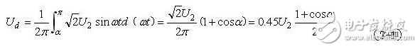
Where α is the trigger delay angle, also called the starting angle or the control angle.

θ is the conduction angle and there is

It can be seen from the formula (2-1) that with α↑, Ud↓, the phase shift range is . By adjusting the angle α, the size of the Ud can be controlled. This way of controlling the magnitude of the DC output voltage by controlling the phase angle of the trigger pulse is called phase control.

Generally, the value of the capacitor satisfies R*C=(3-5)T, where R is the load resistance, which is equal to the ratio of the DC voltage of the DC output to the DC output current; C is the capacity of the filter capacitor; T is the rectification The repetition frequency of the post-pulsating DC voltage. After this selection, it is completely possible to supply power to electronic devices that do not have voltage regulation requirements. This formula is not strictly required to obey. If there is a voltage regulator circuit behind the filter, the filter capacitor takes a small point, but the voltage regulator circuit must be fully functional, and the pressure compensation at both ends is very large. It should be a relatively strong voltage regulation capability. As for the withstand voltage of the filter capacitor, for the half-wave rectification and full-wave rectification circuits, the withstand voltage of the filter capacitor is required to be larger than the maximum value of the input AC voltage of the rectifier circuit.

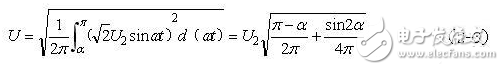
The effective value of the rectified output voltage is:

Generally, the value of the capacitor satisfies R*C=(3-5)T, where R is the load resistance, which is equal to the ratio of the DC voltage of the DC output to the DC output current; C is the capacity of the filter capacitor; T is the rectification The repetition frequency of the post-pulsating DC voltage. After this selection, it is completely possible to supply power to electronic devices that do not have voltage regulation requirements. This formula is not strictly required to obey. If there is a voltage regulator circuit behind the filter, the filter capacitor takes a small point, but the voltage regulator circuit must be fully functional, and the pressure compensation at both ends is very large. It should be a relatively strong voltage regulation capability. As for the withstand voltage of the filter capacitor, for the half-wave rectification and full-wave rectification circuits, the withstand voltage of the filter capacitor is required to be larger than the maximum value of the input AC voltage of the rectifier circuit.

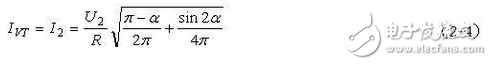
The effective current flowing through the thyristor is:

Generally, the value of the capacitor satisfies R*C=(3-5)T, where R is the load resistance, which is equal to the ratio of the DC voltage of the DC output to the DC output current; C is the capacity of the filter capacitor; T is the rectification The repetition frequency of the post-pulsating DC voltage. After this selection, it is completely possible to supply power to electronic devices that do not have voltage regulation requirements. This formula is not strictly required to obey. If there is a voltage regulator circuit behind the filter, the filter capacitor takes a small point, but the voltage regulator circuit must be fully functional, and the pressure compensation at both ends is very large. It should be a relatively strong voltage regulation capability. As for the withstand voltage of the filter capacitor, for the half-wave rectification and full-wave rectification circuits, the withstand voltage of the filter capacitor is required to be larger than the maximum value of the input AC voltage of the rectifier circuit.

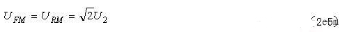
The maximum voltage that the thyristor is subjected to is:

Generally, the value of the capacitor satisfies R*C=(3-5)T, where R is the load resistance, which is equal to the ratio of the DC voltage of the DC output to the DC output current; C is the capacity of the filter capacitor; T is the rectification The repetition frequency of the post-pulsating DC voltage. After this selection, it is completely possible to supply power to electronic devices that do not have voltage regulation requirements. This formula is not strictly required to obey. If there is a voltage regulator circuit behind the filter, the filter capacitor takes a small point, but the voltage regulator circuit must be fully functional, and the pressure compensation at both ends is very large. It should be a relatively strong voltage regulation capability. As for the withstand voltage of the filter capacitor, for the half-wave rectification and full-wave rectification circuits, the withstand voltage of the filter capacitor is required to be larger than the maximum value of the input AC voltage of the rectifier circuit.

According to the definition of power factor, there are:

Generally, the value of the capacitor satisfies R*C=(3-5)T, where R is the load resistance, which is equal to the ratio of the DC voltage of the DC output to the DC output current; C is the capacity of the filter capacitor; T is the rectification The repetition frequency of the post-pulsating DC voltage. After this selection, it is completely possible to supply power to electronic devices that do not have voltage regulation requirements. This formula is not strictly required to obey. If there is a voltage regulator circuit behind the filter, the filter capacitor takes a small point, but the voltage regulator circuit must be fully functional, and the pressure compensation at both ends is very large. It should be a relatively strong voltage regulation capability. As for the withstand voltage of the filter capacitor, for the half-wave rectification and full-wave rectification circuits, the withstand voltage of the filter capacitor is required to be larger than the maximum value of the input AC voltage of the rectifier circuit.

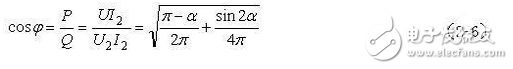
It can be seen that the power factor cos φ is a function of the control angle α. When α = 0°, cosφ is at most 0.707.

3, single-phase half-wave controllable rectifier with inductive load operation (in production practice, most of the load is a resistive load, such as the excitation winding of various motors, electromagnet coil, etc. If ωL ≥ R is called inductive load Such as the field winding of the motor)

The key to analyzing the working condition of the rectifying circuit with resistive load is that the inductor has a resistance to the current change, so the current flowing through the inductor cannot be abruptly changed. The working waveform is shown in Figure 2-2. In order to solve the contradiction that the average value Ud is small when φ is large, a freewheeling diode is connected in parallel across the load of the rectifier circuit, so that no negative portion appears in Ud.

If L is large enough, ωL "R", that is, the load is an inductive load. During the VT off period, the VDR can be continuously turned on, so that the id is continuous, and the id waveform is close to a horizontal line, as shown in Figure 2-4f.

The single-phase half-wave controllable rectifier circuit is characterized by simplicity, but the output current ripple is large, and the secondary side current of the transformer contains a DC component, which causes the transformer core to be DC magnetized. In order to make the transformer core unsaturated, it is necessary to increase the cross-sectional area of ​​the core and increase the capacity of the device. This circuit is rarely used in practice. The main purpose of analyzing this circuit is to establish the basic concept of the rectifier circuit by using its simple and easy to learn characteristics.

Single half-wave rectification circuit diagram:

Generally, the value of the capacitor satisfies R*C=(3-5)T, where R is the load resistance, which is equal to the ratio of the DC voltage of the DC output to the DC output current; C is the capacity of the filter capacitor; T is the rectification The repetition frequency of the post-pulsating DC voltage. After this selection, it is completely possible to supply power to electronic devices that do not have voltage regulation requirements. This formula is not strictly required to obey. If there is a voltage regulator circuit behind the filter, the filter capacitor takes a small point, but the voltage regulator circuit must be fully functional, and the pressure compensation at both ends is very large. It should be a relatively strong voltage regulation capability. As for the withstand voltage of the filter capacitor, for the half-wave rectification and full-wave rectification circuits, the withstand voltage of the filter capacitor is required to be larger than the maximum value of the input AC voltage of the rectifier circuit.

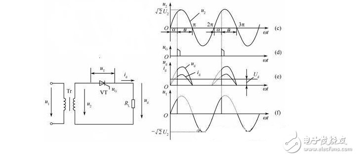
3000W Three Phase AC Source System

Product Introduction:

APM 3 Phase Ac source SPS300VAC3000W is capable of delivering 3000VA of output power.3 Phase Ac Power Source is a 3-phase output programmable AC Power Supply which provides with high power density. With high speed DSP+CPLD control, high frequency PWM technology, active PFC design, It is able to provide not only stable DC/AC output power, but also 3-phase / 1-phase output. This AC power supply is featured with high power density, high reliability and high precision, meanwhile it possesses operation interface of touch screen and keys manually. It is able to analog output normal or abnormal power input for electrical device to meet test requirements, which is applicable to electric, lighting, aviation sectors, etc. It could be applied to enterprise`s production test as well.


Product Features:

● Large touch color screen, possess complete functions and easy to operate

● AC+DC mixed or independent output mode for voltage DC offset simulation

● Capable of setting output slope/phase angle, 0~359.9°

● Output frequency 15~1000Hz, capable of setting output slope of voltage and frequency

● High output crest factor could satisfy surge tests requirements

● Multiple current measuring level selection. Increase measurement accuracy

● Standard USB data interface, support CSV file waveform import

● OCP/OVP/OPP/OTP/ Short circuit protection

● Built-in power meter, which is capable of measuring 15 electrical parameters per phase, including voltage, current, power, etc

● With reverse current protection to avoid current flowing backward

● Capable of setting voltage and current output restriction, support for constant current output mode


Basic Functions:

1. Adjustable Phase Angle/Slope

Adjustable Phase Angle/Slope is applicable to verification test of ON/OFF inrush current testing. This function is applicable to start inductive or capacitive load with large capacity to avoid high current when instantaneously start the device.

2.High Output Current Crest Factor

The surge current could reach 5-6 times of the rated current, especially suitable for inrush current testing.
3. Output Simulation Sequence and Disturbance Simulation

Capable of simulating power line disturbance simulation test.


Advanced Functions:

1.Built-in IEC Standard Test
Built-in IEC standard test could be recalled directly.

2.3-Phase Operation and Parallel Mode

Support 3-phase operation, 3 units in parallel

3000W 3 Phase AC Source, 3000W 3 Phase AC Power Supply, 3-Phase/1-Phase Output, Programmable Ac Power Sources,3 Phase source

APM Technologies Ltd , https://www.apmpowersupply.com