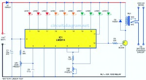
Building a circuit diagram for a battery level indicator is quite straightforward. Typically, on mobile devices, the battery status is represented by bars or points that visually indicate charge levels. This design provides a similar system but uses LEDs instead. The circuit we’re discussing here can display the battery percentage of an electronic device using a series of ten LEDs. Each LED corresponds to a specific percentage range, making it simple to understand the remaining battery capacity at a glance. For instance, if three LEDs are lit, it signifies approximately 30% battery life left.
This particular setup functions similarly to how phones handle battery indicators, except it relies on a single comparator IC (LM3914). This chip divides the battery’s full charge into ten distinct segments, each representing a different percentage range.
The circuit draws its power directly from the device’s own battery. It features ten LEDs arranged in a linear fashion, with each LED color-coded to match specific voltage thresholds. Red LEDs (LED1 through LED3) signal that the battery is below 40%, orange LEDs (LED4 through LED6) show levels between 40% and 70%, while green LEDs (LED7 through LED10) represent capacities above 70%. By adjusting the variable resistor VR2, located between pins 6 and 7, you can tweak the brightness of the LEDs for better visibility.
Diode D1 ensures protection against reverse polarity connections. When the battery reaches full charge, the tenth LED turns on, triggering transistor T1 to activate relay RL1. This action stops further charging via the normally open (N/O) contact of the relay.
To calibrate the circuit, connect it to a 15V adjustable regulated power supply and initially set it to 3V. Adjust VR1 until LED1 lights up. Then incrementally raise the voltage in steps of 1.2V, ensuring that each subsequent LED (LED2 through LED10) illuminates correctly as the voltage increases.
Once calibrated, the circuit can accurately reflect any voltage level within its range. Given that there are ten LEDs, each LED represents roughly 10% of the total battery capacity. To test the circuit, connect the battery voltage across the input probes. The number of lit LEDs will immediately reveal the current state of the battery—five lit LEDs correspond to around 50-59% battery life.
For practical use, construct this circuit on a universal printed circuit board (PCB). After calibration, place the PCB inside your device. You’ll need ten LEDs, variable resistors for adjustment, and two terminal holes for battery input. With this setup, monitoring your battery health becomes both intuitive and efficient.
The JUK universal Screw Terminal Block series has the typical features which are decisive for practical applications:
l The universal foot allows the terminal blocks to be easily snapped onto the NS35 or NS32 DIN Rail with G shape.
l Closed screw guide holes ensure screwdriver operation perfect.
l For terminal block with different wire cross-sectional areas, complete accessories are available, such as end plates, partition plates, etc.
l Potential distribution achieved by fixed bridges in the terminal center or insertion bridges in the clamping space.
l Same shape and pitch Grounding Terminal Blocks as the JUK universal series.
l Adopt ZB marker strip system,achieve unified identification.
Screw Terminal Block Block,Screw Disconnect Terminal Block,Cage Spring Terminal Block,Spring Clamp Terminals
Wonke Electric CO.,Ltd. , https://www.wkdq-electric.com