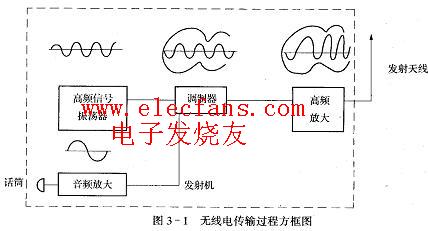
In the process of radio broadcast transmission, the broadcast station broadcasts the program by first converting the sound into an audio electrical signal through the microphone, and then modulating it by a high-frequency signal (carrier) after amplification. At this time, a certain parameter of the high-frequency carrier signal corresponds to the audio signal. Changes, so that the audio signal we want to transmit is included in the high-frequency carrier signal, the high-frequency signal is then amplified, and then a high-frequency current flows through the antenna to form a radio wave that is emitted outward, and the radio wave propagation speed is 3 × 10⁸m / s, this radio wave is received by the radio antenna, and then amplified, demodulated, and restored into an audio electrical signal, which is sent to the speaker voice coil, causing the corresponding vibration of the paper cone, and the sound can be restored, that is, the transmission of sound and electricity is converted— — The process of electroacoustic conversion.
The frequency of the medium wave (high-frequency carrier frequency) is specified as 525-1605 kHz (thousand cycles).
The short wave frequency range is 3500-18000kHz.
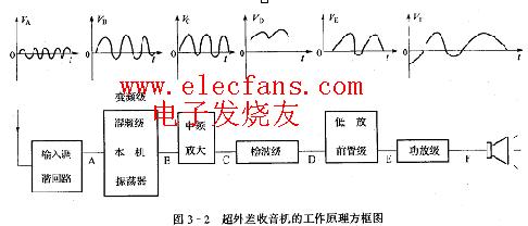
Figure 3-2 is a block diagram of the working principle of an AM super-heterodyne radio. The high-frequency signal received by the antenna passes through the input circuit and the local oscillation frequency of the radio (the frequency is higher than the external high-frequency signal by a fixed intermediate frequency. 465KHZ) into the frequency conversion tube together for mixing-frequency conversion, a new frequency is generated in the load circuit (frequency selection) of the frequency conversion stage, that is, the intermediate frequency generated by the difference frequency (internship Figure 3-2 B), the intermediate frequency only changes the carrier The frequency, the original audio envelope has not changed, the intermediate frequency signal can be better amplified, the intermediate frequency signal is detected and filtered out of the high frequency signal (D in Practice Figure 3-2). After low-amplification and power amplification, the speaker is pushed to make a sound.
A brief description of the working principle of this machine. For the circuit diagram, see C1 and B1 shown in Practice Figure 3-3 to form the antenna input circuit. VT1, B2, B1, C form the frequency conversion stage. VT1 is a frequency conversion tube. The primary coil and C constitute a variable frequency load. C1 and B2 form the local oscillation circuit, C6 is the oscillation coupling circuit, VT2 and VT3 form the intermediate frequency amplifier circuit, 2AP9 is the detection circuit, R9 is the volume potentiometer (with power switch), and C16 is the high frequency coupling capacitor.
VT4 and VT5 are the front low-frequency amplifying stage, VT6 and VT7 form a class B push-pull power amplifier. R16, C21, C17 are power wave circuits. R1, R2, R3, R4, R5, R6, R7, R12, R10, R11, R13, R17, R18 are DC bias resistors at all levels.
â‘ Circuit analysis of the whole machine, familiar with the installation position of components on the printed board.
â‘¡Welding and installation of components (check the quality of components during installation).
â‘¢ Check the circuit, check the following contents with the installed radio and the circuit schematic diagram.
a. Check the model, installation position and pins of the transistors at all levels.
b. Check the installation sequence of the middle and middle levels of all levels, and check whether the primary and secondary leads are correct.
c. Check whether the positive and negative connections of the electrolytic capacitors are correct.
d. Whether the primary and secondary installation positions of the magnetic antenna coil wound in sections are correct.
e. Measure the resistance of the whole machine with the R × 100 file of a pointer multimeter, connect the negative lead of the power supply with a red test lead, and connect the positive lead of the power supply with a black test lead.
After the above check is correct, the 4.5 volt power supply can be connected.
Commissioning of superheterodyne radios. Newly installed radio. It must be adjusted to meet the requirements of the performance index. The adjustment content includes: adjusting the operating point of transistors at all levels, adjusting the intermediate frequency, adjusting the coverage (that is, the scale), and adjusting it (adjusting the frequency tracking or sensitivity).
The adjustment contents and methods are described below:①Adjust the static working point: the function of each transistor is different, and the working point is different. The adjustment of the static working point at all levels is through the absence of a signal (local oscillation stop) when there is no external signal. The magnitude of the voltage is measured separately. Adjust R1, R4, R12, R17, R18 in steps to make the voltage of VT1 level -0.5 ~ 0.7V. The voltage on R6 of VT2 level is -0.5 ~ 0.7V. The voltage on VT3 level R7 is -0.25 ~ 0.4V, the voltage on VT5 level R14 is -0.7 ~ 0.9V, VT6, VT7 level is the common collector level current is 2 ~ 6mA.
â‘¡Adjust the intermediate frequency: the purpose is to adjust the resonance frequency of the three intermediate-period transformers (intermediate frequency tuning loop) to a fixed intermediate-frequency frequency of 465KHZ. Since the intermediate frequency used is new, the general manufacturer has adjusted to 465KHZ, so when debugging, receive a certain Radio station, use a non-inductive screwdriver to adjust the middle magnetic core. The adjustment sequence is from the rear stage to the front stage, that is, first adjust Bz3 and then Bz2 until the loudest speaker sound. 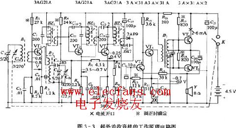
â‘¢Frequency adjustment coverage (frequency range of the radio is adjusted from 535 to 1605kHz): adjust the upper dial of the fashion so that the double-connected variable capacitors are all screwed in and out of the pointer on the line of the dial 530-1630 thousand cycles, and rotate Double connected variable capacitors to align the pointer to the 640 thousand cycle scale (Central People's Broadcasting Station). Use the magnetic core of the non-inductive screwdriver to oscillate the oscillating coil to listen to the 640 thousand cycle radio broadcast. Near the scale of 1500 thousand cycles. Adjust the oscillation circuit fine-tuning capacitor C3 to listen to radio broadcasts near 1500 thousand weeks, so the high-end and low-end are repeatedly adjusted several times.
â‘£ The purpose of unified adjustment (adjustment of frequency tracking) is to make the local oscillation frequency in the receiving frequency range (middle band 535 ~ 1650kHz) and far higher than the external signal frequency 465KHz, that is, the local oscillation frequency range is 1000kHz ~ 2070kHz. Therefore, C1 and C2 double-connected variable capacitors with the same capacitance are used for synchronous adjustment. Usually, the three points of high, medium and low within the selected frequency range are used for tracking, that is, the three-point unified adjustment. The oscillation circuit is connected in series with a padding capacitor C and a parallel fine-tuning compensation capacitor C, and a compensation fine-tuning capacitor C is connected in parallel with the input circuit for specific adjustment, and then the input circuit compensation capacitor Cz is adjusted to make the volume loudest.
The mid-end adjustment is to listen to the radio near 1000KHZ, so that the sound is the loudest. At this time, adjust the C piece on the flower piece of the double-connected capacitor moving piece, and move the film distance. If the input is reduced when the flower is dialed, the mid-end will not be detuned. If the input is increased, the edge lace needs to be compensated when the input is increased, and the capacitance of the pad can also be changed. .
Winnowing Machine,Winnowing Rice,Seed Winnowing Machine,Grain Winnowing Machine
Hunan Furui Mechanical and Electrical Equipment Manufacturing Co., Ltd. , https://www.thresher.nl