The radome serves as a dielectric enclosure that protects the antenna from harsh environmental conditions, ensuring its durability and operational integrity. However, the presence of the radome can also impact the antenna's electrical performance, such as altering the radiation pattern, increasing power transmission loss, and introducing aiming errors. With the widespread adoption of ANSYS HFSS in antenna and feed system design, simulation-based workflows have become well-established. These advanced methods are driving the development of RF modules toward higher performance and greater integration. As antenna specifications continue to evolve, the electromagnetic design of radomes—particularly their integrated design and co-simulation with antennas or antenna arrays—has become a critical challenge.
The radome is a vital component in complex antenna systems, and its electromagnetic design poses significant challenges. Many radomes are large in size and composed of complex materials. When the internal structure includes a waveguide slot array, the rotation angle of the antenna must be considered, which introduces high demands on calculation accuracy due to the aiming errors and slope variations caused by rotation. Therefore, full-wave simulation technology is essential for an accurate overall analysis of the antenna array and radome system. Such large-scale simulations require advanced algorithms and parallel computing techniques to manage the computational load effectively.
**1. New 3D Component Function Enables Faster Integrated Modeling of Radome and Antenna Array**
In traditional R&D processes, radomes and antennas are often developed by separate teams. To study the electrical performance of the radome, it is necessary to integrate the antenna or antenna array with the radome to achieve more accurate and reliable results. This integration allows for the consideration of complex near-field effects. However, the safe transfer of simulation models remains a critical issue during the development process.
The improved 3D Component function in HFSS enables users to save their simulation models as 3D Components. These components include all necessary settings, such as 3D geometry, material properties, ports, boundary conditions, meshing, modes, and hybrid algorithm configurations. They can then be directly used in new simulations. In the latest version of HFSS 2016, a new encryption feature was introduced, allowing users to protect their models with passwords and hide internal structural details. From the user’s perspective, the 3D Component appears as a black box, yet full performance data can still be obtained through simulation, ensuring secure model delivery and protecting intellectual property.
In this test case, the internal structures of the waveguide slot array were hidden, leaving only the outermost air box visible. In a new project, we inserted the pre-built 3D Components of the radome and waveguide array, adjusted their positions, and completed the integrated model with just a few simple steps. No additional material properties, ports, or boundary conditions needed to be set up, as these were already included in the 3D Component. Due to the encryption, only the unhidden parts of the model were visible.
**Basic Model Information:**
- **Radome:** Single-layer dielectric cover, height 650 mm, bottom diameter 320 mm, thickness approximately 2.5 mm.
- **Waveguide Slot Array:** Round aperture, diameter 185 mm, four-port feeding.
- **Operating Frequency Band:** 15 GHz.
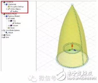
*Figure: 3D Component assembled integrated model, the internal details of the antenna array are completely hidden*
**2. FEM-IE Hybrid Algorithm Reduces Solution Space**
When simulating large radomes made of dielectric materials, the FEM-IE hybrid algorithm in HFSS is the optimal choice. High-frequency asymptotic methods like PO and UTD are effective only for pure metallic structures and cannot handle the complex electromagnetic behavior within dielectric radomes. The multiple reflections inside the radome complicate the beam path, making it difficult for traditional ray-based methods to provide accurate results. The method of moments struggles with generating Green's functions for multi-layer dielectric structures and solving cavity problems involving arbitrary three-dimensional surfaces and waveguide slot arrays. While the finite element method excels at handling complex 3D structures and antenna arrays, the large solution space leads to high computational costs and reduced efficiency.
By combining the finite element method (FEM) with the integral equation (IE) approach, the FEM-IE hybrid algorithm in HFSS significantly reduces the solution space, lowering computational requirements and saving time and resources. In HFSS, the FE-BI technique is used, where the finite element method is applied within a defined boundary, while the boundary surface uses the integral equation method. This allows a large portion of the air region between the radome and the antenna to be excluded from the finite element domain, conforming precisely to the antenna structure.
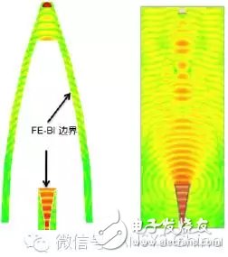
*Figure: FE-BI boundary (left) can significantly reduce solution space compared to finite element radiation boundary (right)*
40L Agriculture Drone,Agricultural Spraying Drone,Drones Agriculture Sprayer,Agricultural Sprayer
Xuzhou Jitian Intelligent Equipment Co. Ltd , https://www.jitianintelligent.com