First, let's explore the working principle of the circuit.
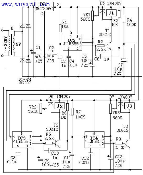
The circuit is built around three monolithic integrated circuits, specifically the LM555 timer ICs. Each of these ICs functions as a monostable multivibrator, serving as a timing control unit. Together, they form a three-stage loop timing system that operates sequentially. When power is first applied, the reset pins (pin 4) of IC3 and IC4 are connected to automatic reset circuits with large time constants—comprising R4 & C7 for IC3, and R7 & C11 for IC4. This causes IC3 and IC4 to be in a reset state, meaning their output pins (pin 3) remain low. As a result, transistors T2 and T3 are turned off, and relays J2 and J3 are released.
Meanwhile, the reset pin (pin 4) of IC2 is directly connected to the positive power supply. At power-on, the voltage across capacitor C3 cannot change abruptly, which triggers the trigger pin (pin 2) of IC2. This puts IC2 into a temporary unstable state, causing its output (pin 3) to go high. This turns on transistor T1, activating relay J1, which then powers the connected electrical device. Simultaneously, the power supply begins charging capacitor C5 through potentiometer VR1. Once the voltage across C5 reaches two-thirds of the supply voltage (approximately 4V), IC2 exits its temporary state, and its output returns to low. This turns off transistor T1, releasing relay J1, and the connected device is powered down.
By adjusting the values of VR1 and C5, the activation time of relay J1 can be controlled. At the moment when IC2’s output goes low, a differentiating circuit made up of capacitor C6 and resistor R3 generates a negative spike at the trigger pin (pin 2) of IC3, which triggers it into a temporary state. IC3’s output (pin 3) then goes high, turning on transistor T2 and pulling in relay J2, which powers the next connected device. Adjusting VR2 and C9 allows control over the duration of this stage.
When the second stage ends, a differentiating circuit involving C10 and R6 creates a negative spike at the trigger pin of IC4, initiating its transient state. Its output goes high, turning on transistor T3 and engaging relay J3, which powers the third device. By modifying the values of VR3 and C13, the timing of this stage can be adjusted. Finally, when the third stage concludes, the differentiating circuit formed by C3 and R1 triggers the first stage again, completing the cycle and enabling continuous, sequential timing control.
Battery Energy Storage System,Battery Energy,Lithium Battery,Lithium Ion Battery,Pylontech Battery
Wuxi Sunket New Energy Technology Co.,Ltd , https://www.sunketsolar.com