Since the original wireless killer application, voice, required uplink and downlink with the same capacity, many wireless data networks were originally designed to provide symmetric data capacity. The licensed and auctioned spectrum blocks are also paired, as this is well suited for Frequency Division Multiplexing (FDD) protocols, which are well suited to operators and users when voice is the primary application.
However, with the rapid development of broadband data services, the requirements for the network have become asymmetrical. In other words, the downlink and uplink loads on the network are no longer balanced because the amount of downloads by users is usually much larger than the amount uploaded. When using symmetrically configured data services, this asymmetrical data requirement will quickly result in the downlink reaching full capacity and the uplink utilization being severely under-utilized.
In this case, the Time Division Multiplexing (TD) protocol has a great advantage because it can adjust the relative bandwidth allocation between the uplink and the downlink by adjusting the slot arrangement of the uplink and downlink transmissions. . With efficient time slot scheduling, operators can operate their networks with higher utilization than symmetric models. TD-LTE allows the bandwidth allocation to be dynamically modified according to the specific needs of the network, updating the uplink and downlink transmission slot arrangements within a single channel, thereby helping operators operate the LTE network with higher utilization.
The key to a robust and reliable TD-LTE test method is to ensure that the test equipment supports multiple critical requirements. In the real world, the uplink and downlink coexist in the same spectrum, so effective test equipment designed to support the successful deployment of TD-LTE must also provide these same features. In particular, the test equipment must support bidirectional test work with phase and amplitude balanced uplink and downlink channels.
Advanced wireless test equipment such as channel simulators can provide the real world environment necessary for TD-LTE testing. The test results generated by integrating the channel simulator in a test solution that supports device and infrastructure testing can better reflect the facts that occur in the real world. As the bandwidth and development requirements for the MIMO protocol continue to increase, channel emulators that can simultaneously support the various RF requirements required for TD-LTE testing and related models that implement typical activities in the real world will be key to efficient testing.
Actual test requirements for TD-LTE systems and equipment
MIMO protocols such as LTE are now more affected by the changing radio environment in the real world than ever before, and the correlations exhibited by the channel models used in the testing process have a large impact on them. While some basic test projects use standard channel models, more advanced test solutions can support both TD-LTE solution testing in the air and in repeated radio field conditions in the lab.
Standard laboratory tests using wired connections can produce repeatable results, but lack real-world and airborne testing through the entire antenna. While aerial testing (such as driving tests) can represent the real world, tests such as driving tests lack repeatability. This is because there are many variables that affect performance in real-world testing, such as channel conditions that vary due to seasonality and network load; the cost of actual tests like driving tests is also high.
To compensate for this gap between the lab and the actual air test, the channel simulator can be used in the lab's test platform. The channel simulator repeats the channel propagation conditions in the real world in a controlled and repeatable manner by using complex channel models and numerous programmable parameters (Figure 1). The integrated channel simulator provides bidirectional operation (downlink and uplink directions work simultaneously) through independent programmable channel characteristics in both directions. By using a channel simulator, we can verify radio design and performance, increase test coverage, and shorten test cycles to deliver higher quality products to the market in less time.
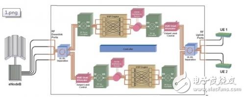
Figure 1: Schematic of a point-to-multipoint test case with channel emulation, where each user equipment (UE) has a fully bidirectional MIMO channel that can realistically create air conditions again.
Data communication technologies such as those used in TD-LTE require high system dynamic range and excellent RF fidelity. These radio systems often use advanced digital modulation techniques to increase capacity. A good example is 64QAM (Quadrature Amplitude Modulation), which carries 6 bits per symbol per OFDM subcarrier. In addition, technologies such as OFDMA further improve the operation of the system and support scalable capacity. These technologies, combined with multi-antenna technology MIMO, ultimately enable the system to provide scalable, reliable capacity to mobile stations with aggregated downlink data rates exceeding 100 Mbps and upstream data rates exceeding 50 Mbps.
But these performance improvements come at a price. Higher order modulation techniques require higher dynamic range and linearity. A 64QAM signal may require a signal-to-noise ratio (SNR) of more than 20 dB to achieve better performance than the target maximum block error rate. OFDM systems transmit many small subcarrier frequencies, which will result in a wide range of variations in instantaneous power levels; peak to average power ratios (PAPR) greater than 10 dB are not uncommon. In a typical frequency selective fading environment in mobile communications, some OFDM subcarrier frequencies may be greatly degraded, and some may not, thus further increasing the dynamic range requirements. The TD-LTE standard currently implements uplinks using SC-FDMA, and is specifically designed to mitigate the effects of deep fading, thereby reducing the power consumption of user equipment.
Input dynamic range of the channel simulator
Several factors related to input power need to be considered when selecting a channel emulator for use with a 3GPP TD-LTE device. These considerations include input power range, peak power, and signal-to-noise margin.
The transmitted signal of a 3GPP LTE device may have a very wide dynamic power range. Although the average power may have some maximum value, the PAPR may exceed 10 dB when using OFDM technology, so the system must adapt to this maximum. Even with SC-FDMA used in transmitters like 3GPP TD-LTE user equipment, PAPR still exists and may exceed 8 dB. Mobile devices also implement transmit power control to change their output power, usually their output power is The function of the eNodeB distance. TD-LTE transmit power control may result in actual power variations of 63 dB or higher. In addition, a sufficiently high signal-to-noise ratio (SNR) must be maintained when the device transmit portion employs higher order modulation, such as 64QAM. When connected to 3GPP TD-LTEb user equipment, a channel simulator that allows direct connection of devices with transmit power from +23 dBm to -40 dBm, while also having sufficient PAPR and SNR margin, will provide a robust and efficient test configuration.
Bidirectional and phase balance
Time-division multiplexed signals present unique challenges to the design of test equipment. The signal path for the FDD protocol is not required to support the phase balance when performing bi-directional testing, as both the uplink and downlink operate in different spectrums and follow their own pilots. However, the TD protocol requires that the uplink and downlink paths be balanced so that the two-way connection can be properly simulated. This is especially important when the base station is able to control downlink transmissions using information from the uplink.
Fading and noise floor
The fading channel simulator is used to provide true fast fading conditions; ideally, the simulated fading conditions will match what is observed by users of devices on the service provider network. For OFDM signals such as those used in 3GPP TD-LTE, the amplitude of some subcarrier frequencies may fade or fall by 20 dB or more due to frequency selective fading. Since each subcarrier frequency is a modulated signal, this transient drop in signal amplitude must be considered along with the noise floor of the channel simulator device when modulation up to 64QAM is employed.
For example, if a signal with an average output power of -40dBm is instantaneously reduced by 20dB due to fading, the amplitude will be -60dBm. To maintain a sufficient signal-to-noise ratio of 25dB under the 64QAM mechanism, the noise floor of the test equipment It should not exceed -85dBm. Test equipment suppliers often use noise power spectral density to represent the noise floor. Assuming a 25C, 10MHz wide signal (this is a typical signal in 3GPP LTE), the noise power spectral density of the test equipment needs to be lower than -155dBm/Hz, so that the signal fidelity can be guaranteed even under fading conditions. . If the noise floor exceeds this value, then it is possible that when the simulator provides a fading channel, the simulator will also introduce a noise level that may cause the receiver to demodulate the error, which is not due to the noise of the device under test. The noise floor of the channel simulator is directly caused.
The meaning of beamforming technology
In the TD-LTE environment, many service providers and equipment vendors are considering deploying beamforming technology. By concentrating the transmitted energy in the beam:
Can reach further distances;
Use less energy to reach the same distance;
Can reduce interference;
Can increase network capacity;
System performance will be improved overall.
The beamforming algorithm is known for its algorithmic basis for selecting beamers. Specific to TD-LTE, we must consider the natural nature of the interchange of wireless space; that is, the wireless path of the downlink looks exactly the same as the wireless path of the uplink. When signals are transmitted in a wireless environment, there are also cases of multipath reflection, wireless channel change, phase change, and the like. In general, beamforming algorithms take advantage of some of the characteristics of the air interface, such as channel variations and interchangeability.
Channel simulation provides a means of regenerating airborne conditions in the laboratory that can be used to test and test different equipment by standard. Channel simulation can be used to verify improvements and performance gains due to beamforming algorithms. However, performing robust beamforming device testing in the lab requires the use of a two-way channel simulator and requires interchangeable and balanced paths in a wired lab environment.

Figure 2: Beamforming.
This is because the beamforming algorithm relies on the phase and amplitude information of the uplink to adjust the antenna field pattern of the downlink. The exchange of channel estimates and other signaling information takes place continuously between the base station and the mobile station, thus requiring a two-way connection in a laboratory environment. Interchangeability means that the transfer function of each path in the MIMO system looks exactly the same in both directions, and the impulse response hij(t) in both directions must also be the same (Figure 3).
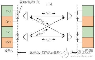
Figure 3: Transfer function of a beamforming MIMO system. It's worth noting that the channel must be end-to-end interchangeable, not just internal to the simulator.
In fact, the test equipment used for beamforming must ensure that the channel phase of the downlink passes the calibration equal to the phase of the uplink channel, that is, the DL needs to be equal to UL, and the balance should also be end-to-end, ie the antenna from the eNodeB. The connection point of the port to the connection point of the antenna port of the mobile station requires a similar amplitude balance for the UL and DL paths (Fig. 4).
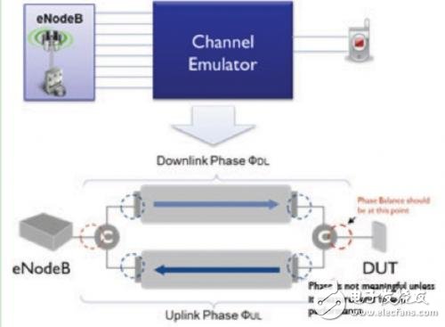
Figure 4: Impact of network load on cellular edge performance.
Terminal equipment located at the edge of the cell generally increases the transmit power to the maximum allowable value in order to ensure continuous robust communication. However, this will quickly lead to the situation where the terminal device can only send one resource block in any given time period. Any attempt to send more than one resource block will extend all available transmit power to more resource blocks, thereby narrowing the maximum range.
However, in fact TD-LTE can provide cellular edge performance equivalent to FDD performance, because almost all cells usually have more than one user, so each device will be limited to a single resource block per unit time, and TD-LTE Or what is the maximum capacity of FDD LTE.
Verification of this performance can be done using a variable AWGN noise source. AWGN noise can well approximate the noise seen by a certain device due to other cells/cells in neighboring terminal devices.
Summary of this article
The rising demand for wireless broadband data is driving the popularity of TD-LTE worldwide. In the case of TD-LTE, the uplink and downlink transmission time slots on a single channel can be adjusted to modify the bandwidth allocation according to the specific needs of the network. This can help operators improve the utilization of LTE networks, but the protocol used presents a unique challenge to device design because it requires balanced uplink and downlink paths to properly simulate bidirectional connections.
TD-LTE testing must consider the dynamic range, phase and amplitude balance of the test equipment, and bidirectional characteristics to model TD-LTE deployment scenarios including beamforming. To ensure complete real-world testing of TD-LTE devices and systems, a suitable channel simulator can be carefully selected. In addition to meeting the above requirements, these simulators provide appropriate automation functions and channel models to help bridge the field and laboratory environments and efficiently reproduce real-world conditions in the lab.
- May "Test and Measurement Special" free download!
Benefits of Aramid Fiber:
-
Strong, Flexible, Durable.
-
ZERO signal interference.
-
Extremely light and slim.
-
Passed 1.2m heights drop test.
-
Metal plates inside to be attachable to the magnetic car mount.
-
Weightless feel. Weight less than 14g. One of the lightest case on the planet.
-
Extremely Thin. A slim profile of 0.65mm only.
-
Extraordinary scratch resistant, grippy but non-slippy coating
-
Ridiculously durable and incredibly strong. 5 times stronger than steel at the same weight.
-
No interference to WIFI, GPS, Apple Pay, Wireless charging or your signals.
iPhone 7 Aramid Fiber Phone Case,iPhone 7 Phone Case,iPhone 7 Aramid Fiber Case,IPhone8 PITAKA Magcase,IPhone8 Aramid Fiber Case,Slim Fit IPhone8 Magcase
Shenzhen Aokal Technology Co., Ltd. , https://www.aokal.com