The oscillating current is a type of current whose magnitude and direction vary periodically over time. A circuit that produces this kind of current is known as an oscillating circuit. The simplest form of such a circuit is the LC loop, which consists of an inductor and a capacitor connected in a closed loop.
Oscillating current is a form of alternating current (AC), typically operating at high frequencies. Unlike conventional AC generated by rotating coils in a magnetic field, oscillating current must be produced using an oscillating circuit. This kind of circuit enables continuous energy exchange between the electric field of the capacitor and the magnetic field of the inductor, without any significant energy loss.
An ideal oscillating circuit, or physical model, assumes certain conditions. First, the total resistance in the circuit is zero (R = 0), including the coil and connecting wires. This means there is no energy dissipation in the form of heat. Second, all the inductance is concentrated in the inductor (L), and all the capacitance is concentrated in the capacitor (C), with no additional stray capacitance present. Third, during electromagnetic oscillation, the LC circuit does not emit electromagnetic waves to the surrounding environment. It remains a closed system, where only the mutual conversion between magnetic and electric field energies occurs inside the circuit.
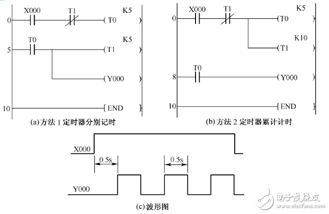
**1. PLC Oscillation Circuit Ladder Diagram and Output Waveform**
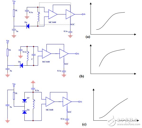
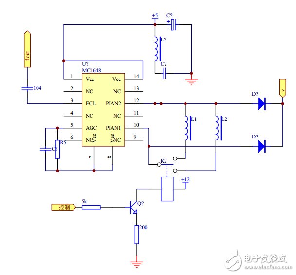
**2. Emitter-Coupled Oscillator Circuit and Output Waveform**
This is a monolithic emitter-coupled oscillator that outputs MECL levels. When operational, the external inductor L and capacitor C form a parallel resonant circuit, allowing for fixed-frequency oscillation. By adding an external varactor diode, the DC bias can be adjusted to create a voltage-controlled LC oscillator. The MC1648 operates at 5V or 5.2V and can reach a maximum frequency of 225MHz. Several common varactor connection methods are shown, including single-tube and double-tube back-to-back configurations. The latter offers better performance in terms of operating frequency and voltage control. The fifth pin of the circuit is connected to AGC (Automatic Gain Control). Adjusting the AGC voltage changes the oscillation amplitude, resulting in different output waveforms. Through AGC tuning, the circuit can produce either a sine wave or a square wave.
As the core component of the system, the oscillator determines the frequency stability and waveform quality. Since it's a high-frequency circuit, the power supply must be carefully managed. Filtering techniques, such as adding an inductor, help suppress interference from the power source and prevent the oscillator from affecting other circuits. To further enhance performance, a metal shielded cover is often used. Based on the selected varactor diode 2CC12B, the maximum operating frequency is 50MHz. However, with proper design, the system can operate within a range of 8–68MHz, with an output frequency up to 60MHz, achieved by adjusting the inductance value.
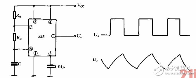
**3. 555 Multivibrator Circuit and Output Waveform**
The 555 timer IC can be configured into various self-excited multivibrators. The basic configuration is shown in Figure (a). Upon power-up, the capacitor C is initially uncharged, causing the trigger pin (pin 2) to be at a low level, which sets the output (pin 3) to a high state. As the capacitor charges through RA and RB, the threshold pin (pin 6) reaches Vcc, switching the output to a low level. The capacitor then discharges through RB and the internal discharge transistor. When the voltage drops below Vcc, the output switches back to high, and the cycle repeats, creating a continuous oscillation. Figure (b) shows the voltage waveform at the output and across the capacitor.
Car Cigaretter Power Cable,Automobile Display Screen Cable,Car Cigarette Lighter Cable,Car Cigarette Lighter Power Cable
ShenZhen Puchen Electronics Co., Ltd. , https://www.szpuchen.com