High-speed signal adjustment technology plays a critical role in maintaining signal integrity as data rates increase. With higher frequencies, the skin effect and dielectric loss become significant factors that degrade signal quality during transmission. These phenomena cause high-frequency components of the signal to be more severely attenuated than low-frequency components, effectively turning the transmission line into a low-pass filter. To counteract this, various signal compensation techniques are employed, such as pre-emphasis, de-emphasis, and equalization.
The impact of high-speed serial links on signal quality is multifaceted. As signals pass through passive links, they face challenges like insertion loss, impedance mismatch, crosstalk, and noise from other channels. These issues can lead to bit errors (BER) and reduce the signal-to-noise ratio (SNR). Additional factors such as ringing, EMI, ground bounce, power supply noise, and environmental changes further complicate signal integrity.
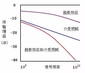
The **skin effect** occurs when alternating current (AC) flows through a conductor, causing the current to concentrate near the surface rather than being evenly distributed. This increases the effective resistance of the conductor, especially at higher frequencies. The **dielectric loss**, on the other hand, refers to energy dissipation due to the polarization and conduction properties of the dielectric material under an electric field. It is often represented by the dielectric loss angle and its tangent, known as the loss factor.
In high-speed signal transmission, the high-frequency components are significantly attenuated, which is why the transmission line behaves like a low-pass filter. This behavior is illustrated in the figure below.
To address these challenges, **equalization technology** is widely used in on-chip solutions. Equalizers help restore the original shape of the signal by compensating for the frequency-dependent losses. There are several types of equalizers, including Continuous Time Linear Equalizers (CTLE), Feed-Forward Equalizers (FFE), and Decision Feedback Equalizers (DFE).
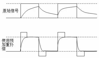
At the **transmitter end**, techniques like **pre-emphasis** and **de-emphasis** are applied. Pre-emphasis enhances the high-frequency components of the signal before transmission, helping to counteract the attenuation caused by the channel. This is particularly useful for improving the signal's edge sharpness, as high-frequency content is mainly found in the rising and falling edges of the signal.
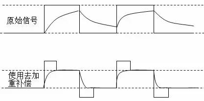
Conversely, **de-emphasis** reduces the amplitude of the signal in areas other than the edges, keeping the rising and falling edges unchanged. While this results in a smaller signal swing and lower power consumption, it also leads to a reduced eye diagram height and less electromagnetic interference (EMI).
However, pre-emphasis and de-emphasis have limitations, especially in environments with crosstalk. To overcome these, **equalization** techniques are introduced at the receiver end. An equalizer acts as a high-pass filter, restoring the signal’s high-frequency components and reducing distortion.

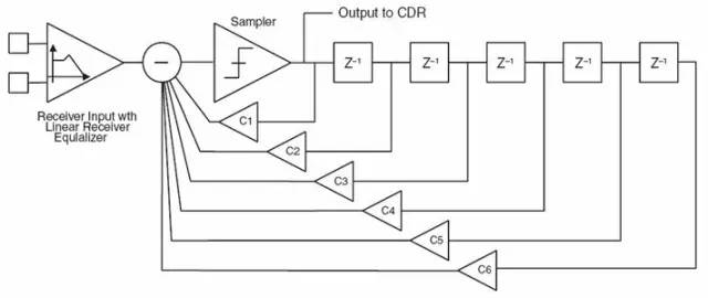
There are different types of equalizers, such as **Feed-Forward Equalizers (FFE)** and **Decision Feedback Equalizers (DFE)**. FFEs are implemented using digital or analog filters, while DFEs use feedback mechanisms to mitigate intersymbol interference (ISI).
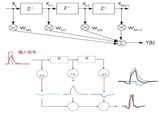
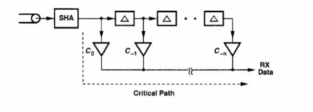
Another type is the **analog FIR filter**, which avoids the need for a high-speed ADC, making it suitable for low-power, high-speed applications. However, it still faces challenges related to delay lines and noise sensitivity.
A **continuous-time filter** eliminates the need for sampling circuits, thereby reducing latency and improving performance. Finally, **decision feedback equalizers (DFEs)** offer better noise immunity but are prone to error propagation if incorrect decisions are made.
An **eye diagram** is a visual representation of signal quality, showing the overlapping waveforms of multiple symbols. It provides valuable insights into signal integrity, including the effects of noise, crosstalk, and timing jitter.
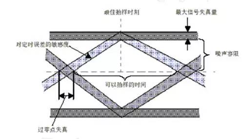
By analyzing the eye diagram, engineers can assess the system's performance and make necessary adjustments to improve signal quality and reliability.
Customized Solar Panel
Customized Solar Panel, 100watt solar panel,200watt solar panel, big solar panel, high efficiency high quality solar modules
different power customized and OEM logo customized solar panel
Customized solar panel data
|
solar cell type
|
mono crystalline half cut cell
|
|
power range
|
50watt to max 700watt
|
|
size and weight
|
different size and different weight if the power is different
|
|
solar panel type
|
monofacial or bifacial
|
|
solar panel color
|
sliver or black
|
Product details and pic


Customized Solar Panel,Noncrystalline Solar Panel Module,Cheap Price Pv Solar Module,Solar Photovoltaic Pv Panel
PLIER(Suzhou) Photovoltaic Technology Co., Ltd. , https://www.pliersolar.com