With the gradual popularization of electric bicycles, lithium batteries, the main energy source of electric bicycles, have also become the focus of attention. Lithium batteries are not the same as nickel-cadmium and nickel-hydrogen batteries. Because of their high energy density, they require high charge and discharge. When overcharge, overdischarge, overcurrent, and short circuit protection occur, the pressure and heat in the lithium battery increase greatly, which is prone to explosion. Therefore, a protection circuit is usually added in the battery pack to improve the service life of the lithium battery. Most of the protection circuits used in the current lithium battery packs of electric vehicles are composed of discrete originals. The control precision is not high enough, the technical indicators are low, and the lithium battery pack cannot be effectively protected. In this paper, a 36 V lithium battery based on single-chip microcomputer is proposed. The battery pack (consisting of 10 3.6 V lithium batteries in series) protection circuit design, using high-performance, low-power ATmega16L microcontroller as the detection and control core, using DC / DC conversion control circuit composed of MC34063 for the whole The protection circuit provides a regulated power supply, supplemented by LM60 temperature measurement and MOS tube IRF530N as charge and discharge control switch, which realizes the status monitoring and protection function of the entire battery pack and single battery, and achieves the purpose of extending battery life.
This article refers to the address: http://

1 protection circuit hardware design
The system takes the single chip as the core of data processing and control, and decomposes the task design into functional modules such as voltage measurement, current measurement, temperature measurement, switch control, power supply, and balanced charging. The overall block diagram of the system is shown in Figure 1.
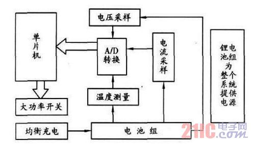
Figure 1 Overall block diagram of the system
The battery pack voltage, current, temperature and other information is applied to the A/D input of the signal acquisition section through voltage sampling, current sampling and temperature measurement circuits. The A/D module converts the input analog signal into a digital signal and transmits it to the microcontroller. As the core of data processing and control, the single-chip microcomputer monitors the performance indexes and status of the battery pack in real time, and controls the driving of the high-power switch according to these state parameters. Thanks to the use of a single-chip microcomputer, the system has great flexibility and is easy to implement various complex controls, so that the system can be easily expanded and improved.
1. 1 ATmega16 L MCU Module
From the perspective of low power consumption and low cost design, the MCU module uses the high performance, low power ATmega16 L MCU as the core of detection and control. ATmega16 L is a low power 8-bit CMOS microcontroller based on enhanced AVRR ISC architecture with 16 kbytes of in-system programmable Flash, 512-byte EEPROM, 1 kbyte SRAM, 32 general purpose I/ O port line, 32 general working registers (JTAG interface for boundary scan, support for on-chip debugging and programming), 3 flexible timer/counters (T/C) with comparison mode (on-chip/external interrupt), Programmable Serial USART, Universal Serial Interface with Start Condition Detector, 8 10-Bit ADCs with Selectable Differential Input Stage Programmable Gain (TQFP Package), Programmable Watchdog Timing with On-Chip Oscillator , an SP I serial port, and six power-saving modes that can be selected via software. Thanks to its advanced instruction set and single clock cycle instruction execution time, the ATmega16 L's data throughput is as high as 1M IPS/MHz, which can alleviate the contradiction between system power consumption and processing speed.
The input and output design of the single chip microcomputer is shown in Figure 2. The 3.3 V voltage obtained by stepping down and stabilizing the power supply section supplies the operating voltage to the microcontroller through port 10; ports 12 and 13 are the input terminals of the reverse oscillation amplifier and the on-chip clock operation circuit and the output of the reverse oscillation amplifier. The working crystal is provided for the single-chip microcomputer; the port 30 is the power supply of the port A and the A/D converter, and is connected to the VCC of the port 10 through a low-pass filter when the ADC is used; the ADC3 and the ADC2 of the port 37, 38 are converted. Detected voltage and current values; ADC1 and ADC0 of ports 39 and 40 are temperature-controlled voltage values ​​after temperature sensor conversion.
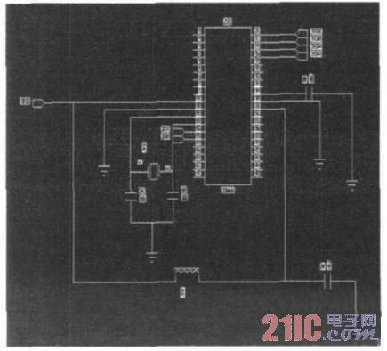
Figure 2 peripheral circuit design of single chip microcomputer
1. 2 regulated power supply module
The regulated power supply is an important part of the single-chip system. It not only provides multiple power supply voltages for the system, but also directly affects the technical specifications and anti-interference performance of the system. The operating voltage of the ATmega16 L MCU is 2. 7~5. 5 V, in order to ensure the stable operating voltage of the MCU is 3.3 V. The voltage regulation part is a DC/DC conversion control circuit composed of MC34063, which is derived from the battery components. The 25 V voltage is stepped down and regulated by the circuit, and the output is 3.3 V for the protection circuit to work. The circuit is shown in Figure 3.
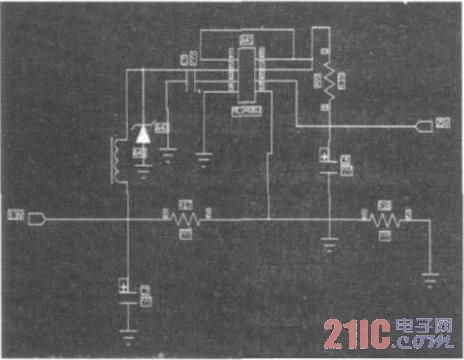
Figure 3 regulated power supply module circuit
1. 3 charging equalization module
Adopt analog circuit scheme. That is, an overvoltage protection circuit is built outside each battery. When the voltage exceeds a predetermined value during charging, the protection circuit automatically closes, so that the battery is discharged through the resistance loop to protect the battery from overcharging. When the battery voltage is reduced to a balanced charging operating voltage of 4.18 V, the protection circuit is automatically disconnected.
1. 4 voltage and current measurement module
The voltage to be tested is sent to the microcontroller for detection by the integrated operational amplifier LM358. The LM358 includes two independent, high-gain, internal-frequency-compensated dual op amps for single-supply operation and dual-supply operation with a wide supply voltage range. It is also suitable for batteries due to its low power consumption. The DC current is detected with the Hall sensor UGN - 3501 M. The UGN-3501M is an integrated Hall sensor with a differential Hall voltage output with a detection sensitivity of 1. 4 V /0. 1T.
The design of the voltage and current detection circuit is shown in Figure 4. The BB and AA connected to the 5 and 6 pins of the operational amplifier LM358 are the charging and discharging voltages to be tested. After amplification, the 7-pin output is output to the MCU for detection. When the detected voltage reaches the overcharge and overdischarge protection voltages. When the microcontroller is controlled to disconnect the charge and discharge circuit. The current detection is completed by the Hall sensor. As shown in Figure 4, the Hall voltage uH output from the UGN-3501M1, 8 pin is connected to the 3, 4 pins of the LM358. After amplification, the ADC3 is output from the 1 pin to the MCU. Overcurrent protection. The UGN-3501M's 5, 6, 7-pin connection adjustment potentiometers compensate for unequal potentials while improving linearity. Adjust the 5, 6-pin external resistor R16 to make the output Hall voltage uH have a good linear relationship with the magnetic field strength.
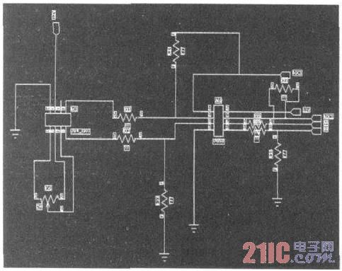
Figure 4 voltage and current detection circuit
1. 5 temperature detection module
The temperature is in the temperature range of -40 ° C to 125 ° C, the operating voltage range is 2. 7 V to the temperature detection and control module is selected as a voltage-type semiconductor temperature sensor LM60. The sensor is a calibrated integrated temperature sensor, the operating temperature range is - 40 ° C to 125 ° C, the operating voltage range is 2. 7 V to 10 V. The signal output is proportional to temperature and the signal size is up to + 6. 25 mV / °C.
The temperature detection circuit based on LM60 is shown in Figure 5. The 3. 3 V power supply output from the voltage regulator part supplies power to the circuit. The temperature of the detection point is converted into a voltage value through the temperature sensor. The ADC0 and ADC1 outputs, and then the ADC0 and ADC1 are sent to the MCU for detection. When the voltage reaches the temperature, the voltage reaches the temperature. When the control is required, the MCU control switch is turned on and off.
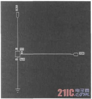
Figure 5 temperature detection circuit
1. 6 switch module
The switch uses MOSFET, the model selects the IR530N of P-channel MOS tube. Working principle: The single-chip control port outputs high level, the power transistor is turned on, the voltage drop between the gate and the drain of the power FET, power field effect The tube is turned on.
2 software design
The system software is written in C language, the processing program adopts modular programming, and the environment in which the program runs is ICCAVR development system.
When the battery pack is unloaded, the system enters power-down mode to minimize power consumption; when the battery pack is connected to the load or charges the battery pack, the microcontroller is activated, and the low-power power-down mode is switched to normal operation. Mode and continue to operate. The flow of the entire program is shown in Figure 6.
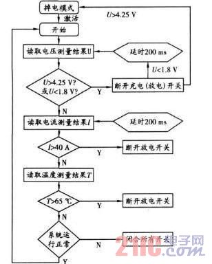
Figure 6 program flow
According to the module distribution of the system, the single-chip microcomputer program is divided into a voltage measurement module, a current measurement module and a temperature measurement module, and each module calls a common A/D conversion function and a delay judgment function to shorten the code length and enhance the program code. Readability. The code for the main function of the program is given below:
Void main ( void)
{
Int ( ) ; / / MCU initialization, open all switches;
Sleep ( ) ; / / MCU enters sleep mode;
Int sign— = 1;
While ( sign = = 1 ) / / determine if the system is working properly;
{ int( ) ;
Dianya ( ) ; / / call the load cell module;
Delay(30000) ;
Delay(30000) ;
Dianliu ( ) ; / / call the flow measurement module;
Delay(30000) ;
Delay(30000) ;
Wendu ( ) ; / / call the temperature module;
Delay(30000) ;
Delay(30000) ;
}
Int ( ) ;
Sign— = 1;
Main ( ) ;
}
3 Conclusion
Through experiments, the protection circuit system realizes all the basic functions. Compared with the traditional battery protection system with separate components, the battery protection circuit system based on single chip microcomputer has the characteristics of small system size, multiple functions, low power consumption and low cost, which can be used in industrial production.
Micro LED light wrapped by clear PVC wire for tangle free, It is easy to pack then the normal one without PVC wire. After adding PVC line, the light color is more transparent and clear. The LED color can be white, warm white, etc.We can make the light in curtain, waterfall, net design. The copper wire won't be etangled. The net light can be used in the big shopping mall for decoration. simple decoration and special design. daily & festival light for indoor & outdoor decoration. Operating by low voltage for safety and convenient use.
Tangle Free Item Lights
Free Item Lights,LED Garden Solar Light,Solar Lawn Light,LED Solar Garden Light
Heshan Jianhao Lighting Industrial Co., Ltd. , https://www.sunclubtw.com