The voltage transformer is a specialized transformer built based on the principle of electromagnetic induction. Its design isn't overly complex. It's employed to adjust the voltage levels on power lines. The main goal of using a voltage transformer is to facilitate the transmission of electrical energy. Consequently, its capacity is quite substantial, typically measured in kilovolt-amperes or megavolt-amperes. On the other hand, the voltage transformer's primary role is to provide voltage readings to measuring instruments and relay protection devices. It helps monitor the voltage, power, and energy in the lines or serves as protection for critical equipment, motors, and transformers in case of faults. Hence, its capacity is relatively small, often just a few volts or tens of volts, rarely exceeding a thousand volts.
**Role and Principle of Voltage Transformers**
The structure of a voltage transformer can be seen in Figure (a). Its purpose is to extend the range of AC voltmeters and isolate high voltages from personnel. Its operational mechanism is similar to that of regular transformers. In practice, the high-voltage winding with numerous turns should be linked to the power supply line where voltage needs to be measured, while the low-voltage winding with fewer turns is connected to the voltmeter, as illustrated in Figure (b).
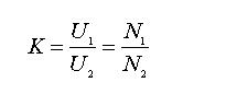
Given that U1/U2=K, U1=KU2, this demonstrates that the voltage of the high-voltage line equals the product of the voltage measured on the secondary side and the transformation ratio (review: transformer working principle, original secondary voltage calculation formula, and transformer transformation ratio). When a voltmeter is used alongside a specific voltage transformer, the voltmeter's scale can be calibrated according to the voltage on the high-voltage side of the transformer. This allows for direct reading of the high-voltage line's voltage without any conversion.
Typically, the secondary winding's rated voltage is standardized at 100 volts. Therefore, voltage transformers used in circuits with varying voltage levels possess different transformation ratios, such as 1000/100, 600/100, etc.
For safe operation, one end of the secondary winding of the iron-core voltage transformer must be grounded. This prevents the high-voltage coil from generating excessive voltage on the ground if the insulation between the high and low voltage coils is compromised, thus ensuring the safety of workers.
**Meaning of Voltage Transformer Models**
A voltage transformer model consists of several parts, each represented by a letter or number:
1st Position: J-PT
2nd Position: D-Single Phase; S-Three Phase; C-Cascade; W-Five Core Columns
3rd Position: G-Dry Type; J-Oil Immersed; C-Porcelain Insulation; Z-Cast Insulation; R-Capacitor Type; S-Three Phase
4th Position: W-Five Core Columns; B-With Compensation Angle Difference Winding
After the hyphen: GH-High Altitude; TH-Wet Hot Zone
Numbers: Voltage Level (KV)
For example: JDZF7-10GYW1
J-Voltage Transformer
D-Single Phase
Z-Cast Type
F-With Residual Voltage Winding
7-Design Number
10-Voltage Class (kV)
GYW1-Plateau Pollution
**Graphical Symbol of Voltage Transformer**
A voltage transformer is a core-based transformer primarily used to proportionally adjust the voltage on a line. According to GB4728-6-84 "Electric Power Generation and Transformation," the voltage transformer symbol is clearly defined in electrical engineering applications.
Voltage Transformer: Potential Transformer referred to as PT, also known as TV in the new national standard, and previously referred to as YH (the first letters of the Chinese words "pressure" and "mutual").
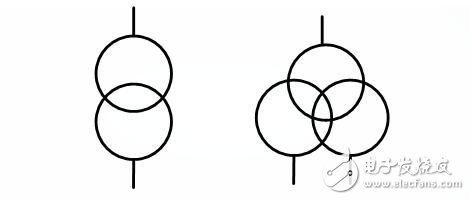
Single-phase voltage transformer symbol
In the left image, two circles represent one primary winding and one secondary winding; in the right image, three circles represent one primary winding and two secondary windings; in another circle, the topmost one is the primary winding, and the others are secondary windings. Both figures above represent single-phase voltage transformers. The three-phase voltage transformer symbol is similar to the single-phase voltage transformer symbol, except three lines representing three phases are added to the terminal, as shown below:
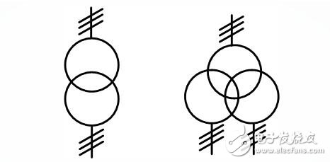
Three-phase voltage transformer symbol
**Selection of Voltage Transformers**
The voltage transformer is a crucial component of the power distribution system. The rationality of the product selection significantly impacts the overall performance of the power system. Selecting the appropriate voltage transformer is also a challenge faced by power practitioners. There are various models and types of voltage transformers, each with unique functions, installation methods, and structures. Let’s delve deeper into the selection process.
Firstly, when purchasing a transformer, it’s essential to understand the primary role of the voltage transformer. Based on its application, voltage transformers can be categorized into protective and measurement types. Protective voltage transformers replace high voltage with secondary components in the power system (such as microcomputer protection devices and intelligent switchgear controls). Measurement voltage transformers are used to monitor and measure the voltage states of primary and secondary circuits.
Secondly, determine whether the transformer will be used indoors or outdoors. If indoors, select an internal voltage transformer; if outdoors, choose an external one.
Thirdly, clarify the voltage level of the power distribution system. Voltage transformers are generally divided into four categories based on voltage level: low-voltage transformers (below 1000V), medium-voltage transformers (3KV to 110KV), high-voltage transformers (220-500KV), and ultra-high voltage transformers (above 500KV). Select the appropriate model according to the project’s voltage level.
Fourthly, consider the insulation type. Voltage transformers are classified as fully enclosed or semi-closed. Ensuring the correct choice is critical to avoid potential issues.
Fifthly, understand the insulating medium of the product. Voltage transformers can be dry, cast, oil-immersed, or gas-insulated. Selection should align with the project’s requirements.
Sixthly, grasp the transformation principle. Voltage transformers can be electromagnetic or capacitive. Electromagnetic transformers convert high voltage to low voltage for secondary equipment, while capacitive transformers extract voltage from capacitors. Choose based on reliability.
By adhering to these principles, voltage transformer selection becomes straightforward, ensuring stable system operations. Feedback from industry peers is always welcome, as we strive to improve and contribute to the power distribution field.
**Voltage Transformer Wiring and Diagram**
A voltage transformer includes a primary winding, a secondary winding, a core, terminals, and insulating supports. Its working principle is depicted in the figure. The primary winding has more turns (N1) and is connected to both ends of the circuit being tested, with an insulation level corresponding to the system's actual voltage. The secondary winding has fewer turns (N2), which can connect to the voltage coil of a measuring instrument or watt-hour meter, with a typical secondary rated voltage of 100V.
When operating normally, the voltage transformer acts as a step-down transformer running on no-load. When the primary winding is connected to the power supply voltage, a no-load current flows through it, generating magnetic flux in the core, inducing an induced voltage in the secondary winding.
U1 - Primary voltage of the voltage transformer, V
U2 - Secondary voltage of the voltage transformer, V
N1 - Number of turns in the primary winding of the voltage transformer
N2 - Number of turns in the secondary winding of the voltage transformer
K - Voltage transformation ratio of the voltage transformer
In the electric energy metering device, after using the voltage transformer, the reading on the electric energy meter is multiplied by the voltage transformer's ratio, providing the actual power consumption. The voltage transformer model consists of alphabetic symbols and numbers, having the following meanings:
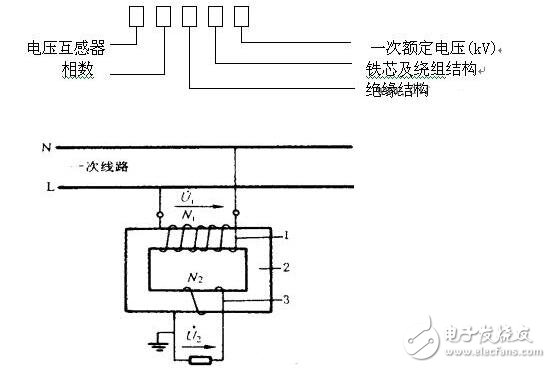
Double winding voltage transformer working principle diagram
**Wiring Method of Voltage Transformer**
(a) Single transformer connection: (b) VV wiring; (c) YY wiring; (d) three-phase five-column voltage transformer wiring; (e) three single-phase three-winding voltage transformer wiring
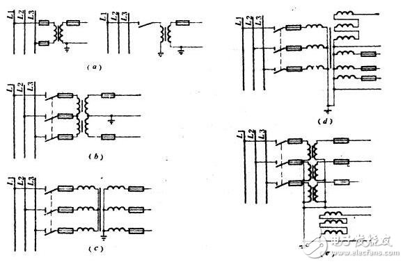
Figure (a) shows the wiring of a single-phase voltage transformer, capable of measuring the line voltage of a system up to 35kV or the relative ground voltage of a neutral-point directly grounded system above 110kV.
Figure (b) illustrates two single-phase voltage transformers connected in a VV-shaped wiring to measure line voltage but not phase voltage. This wiring is widely used in neutral-point indirectly grounded systems.
Figure (c) shows the YY wiring of a three-phase three-column voltage transformer. It can only measure line voltage and cannot be used to measure relative ground voltage. The neutral point of the star-connected secondary winding cannot be grounded because single-phase grounding occurs in the indirectly grounded system. When the grounding voltage is zero relative to ground, the ungrounded voltage increases by a factor of two.
Figure (d) is the Y-Y/Δ wiring of a three-phase five-column voltage transformer. The primary side winding and the basic secondary winding are connected in a star configuration, with the neutral point grounded, and the auxiliary secondary winding connected into an open delta. Thus, the three-phase voltage transformer can measure voltage and relative ground voltage, and can also be used as insulation monitoring for the ground in the neutral-point indirectly grounded system and single-phase grounding relay protection. This wiring is widely used in 6~10kV indoor distribution equipment.
Vacuum Furnace Insulation Tube
Vacuum Furnace Insulation Tube,Small Carbon Fiber Tube,Bare Felt Square Cylinder,Bare Felt Square Carbon Fiber Tube
HuNan MTR New Material Technology Co.,Ltd , https://www.hnmtr.com