In "Selecting the Right Battery Charger for Industrial Applications," we discuss stand-alone and host-controlled chargers and external and integrated switching FETs. Let us now look at the different charging topologies.
First, we must better understand the battery charger features: Dynamic Power Management (DPM) and Dynamic Power Path Management (DPPM). These two functions are closely related to the charging topology and are equally important. Different topologies determine the performance of DPM and DPPM and the total cost associated with the different components selected. For low-power applications, NVDC chargers have drawn attention with their lower cost and DPM/DPPM capabilities. For higher power applications, a traditional charging topology is chosen to reduce power consumption.
Adapters with higher output ratings are usually more expensive. To reduce costs, you may want to use a lower rated adapter, but this requires a charger with current-based DPM to prevent the adapter from being overloaded. This protection is to prevent the total system load and battery load from exceeding the total power that the adapter can provide. For example, a charger with current-based DPM such as bq24133 can handle wide input power without overload (Figure 1).
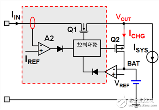
Figure 1: Current-based DPM
In order to achieve peak system performance, the DPPM function is also required so that the charger can operate in a supplemental mode so that the battery can supply power to the system through the battery FET instead of having to be recharged (Figure 2). When designing, you should consider the trade-off between performance and cost. Higher performance is often associated with higher costs. Charger controllers such as TI's bq24610 with DPM and DPPM control can support up to 10A of charging current.
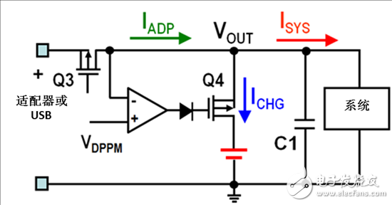
Figure 2: DPPM Current Path Example
Having a better understanding of DPM and DPPM, we can now explore the charging topology. The three most common charging topologies are traditional topologies, hybrid topologies, and narrow VDC (NVDC) topologies.
For traditional topology chargers such as the bq24170, synchronous switch mode independent battery charger and bq24725A SMBus charge controller, the system rail can reach the maximum adapter voltage. If operated from a battery, the system voltage can be as low as the minimum battery voltage. A high voltage input source can cause a large swing of the system rail (Figure 3). The advantage of using this topology is that the system can get the maximum power from the input source. The disadvantage is that the total cost of the solution is high, because components need to handle high power, so they are more expensive.
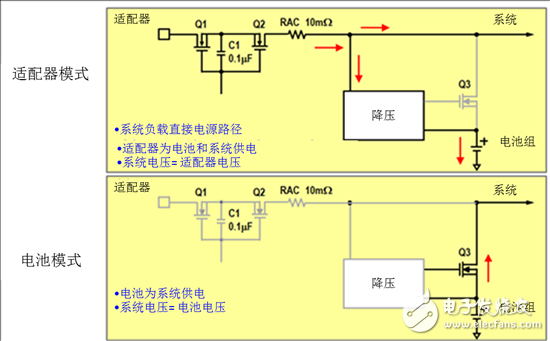
Figure 3: Traditional Charging Topology
In some applications, the system only requires peak power delivery. Adapters designed for normal operation do not meet peak power requirements, and traditional charging topologies do not allow the battery to operate in supplemental mode to provide additional power. The solution to this problem is a hybrid charging topology, as shown in Figure 4.
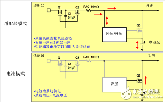
Figure 4: Hybrid Charging Topology
In a hybrid charging topology, the battery can provide additional power to the system for peak power delivery in boost mode. Battery charger ICs such as the bq24735 and bq24780S fall into this category of topology. The hybrid charging topology is also referred to as the "turbocharged" mode. This topology is very popular in notebook applications.
Both traditional and hybrid charging topologies require system rails to handle the same high voltage as the input source. However, in some applications, system rails require lower rated components to reduce cost. In this case, consider the NVDC topology contained in products such as bq24770 or bq24773. By controlling the battery FET, the system voltage is very close to the battery voltage, as shown in Figure 5.
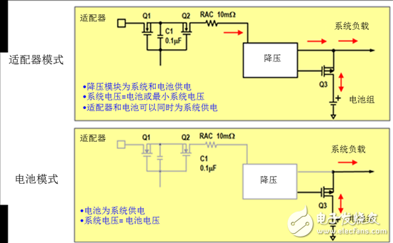
Figure 5: NVDC Charging Topology
Performance, functionality, and solution costs must be balanced when designing a charging system. Choosing the right topology and equipment allows for greater efficiency while maintaining the lowest solution cost.
Transformer Oil Tank,Custom Tank Lng,Wind Power Equipments,Box-Type Transformer
CRRC SHANDONG CO., LTD. , https://www.crrcsd.com