Pulling current and sinking current are parameters that measure the output drive capability of the circuit (note: pull and fill are all for the output, so it is the drive capability). This statement is generally used in digital circuits.
First of all, the pull and sink currents in the chip manual are a parameter value, which is the upper limit value (allowable maximum value) that the chip allows the output terminal to pull and sink current in the actual circuit. The concept to be discussed below is the actual value in the circuit.
Since the output of the digital circuit has only two levels of high and low (0, 1), when the output is high level, the output terminal generally supplies current to the load, and the value of the current supplied is called "pull current"; low level output At the time, it is generally the current that the output terminal needs to absorb the load, and the value of the current absorbed is called “charge (in) currentâ€.
For devices with input current:
Both the sinking current and the sinking current are input, the sinking current is passive, and the sinking current is active.
If the external current flows through the chip pin into the chip, it is called sink current (filled in); if the internal current flows through the chip pin from the chip, it is called pull current (pushed out).
Why can you measure output drive capability?When the logic gate output is low, the current sinking into the logic gate is called sink current. The larger the sink current, the higher the low level of the output. It can also be seen from the triode output characteristic curve that the larger the sink current, the larger the saturation voltage drop and the higher the low level.
However, the logic gate's low level is limited, it has a maximum value of UOLMAX. When the logic gate is working, it is not allowed to exceed this value. The specification of the TTL logic gate specifies UOLMAX ≤ 0.4 to 0.5V. Therefore, there is an upper limit to the sinking current.
When the logic gate output is high, the current at the output of the logic gate flows out of the logic gate. This current is called the pull current. The higher the pull current, the lower the high level at the output. This is because the output stage transistor has an internal resistance, and the voltage drop across the internal resistance causes the output voltage to drop. The higher the pull current, the lower the high level at the output.
However, the logic gate's high level is limited, it has a minimum value of UOHMIN. When the logic gate is working, it is not allowed to exceed this value. The specification of the TTL logic gate specifies UOHMIN ≥ 2.4V. Therefore, there is also an upper limit to the current drawn.
It can be seen that the current and sink current at the output have an upper limit. Otherwise, the current will cause the output level to be lower than UOHMIN when the high level is output. When the output is low, the current will make the output level higher than UOLMAX. Therefore, the pull current and the sink current reflect the output drive capability. (The larger the pull-and-sink current parameter value of the chip means that the chip can be connected to more load because, for example, the sink current is given by the load, and the more the load, the larger the current is injected)
Since the high-level input current is small, in the micro-ampere level, it is generally not necessary to consider that the low-level current is large, at the milliamp level. Therefore, often the low level sink current does not exceed the standard will not be a problem. The fan-out factor is used to illustrate the ability of a logic gate to drive a similar gate. The fan-out factor No is the ratio of the low-level maximum output current to the low-level maximum input current.
In integrated circuits, sinking current, sinking current output, and sinking current output are important concepts.
Pulling and venting, active output current, is the output current from the output port.
Irrigation, passive input current, is flowing from the output port
Suction is the active suction current, which is flowing from the input port.
The current sinking and sinking current is the current flowing from the off-chip circuit through the pin into the chip. The difference is that the sinking current is active, and the current flowing from the input end of the chip is called sinking current. The sinking current is passive, and the incoming current from the output is called sinking current.
The pull current is the output current provided by the digital circuit output high level to the load. When the current is low, the output low level is the external input current to the digital circuit. They are actually the input and output current capabilities.
The sink current is for the input (intake at the input); the pull current (outflow from the output) and the sink current (injected at the output) are relative to the output.
Give an intuitive explanation:

In the figure, PB0 outputs 0, the LED will be on, the current direction of PB0 is flowing to PB0 or ​​sinking current; while PB1 is outputting 1, the LED will be on, and the current direction of PB1 is flowing from PB1, that is, the current is drawn.
In the actual circuit, the current sink is formed by the logic gate input low-level current connected to the latter and injected into the output terminal of the front logic gate. The reader will refer to Figure 18-2-3. Obviously its test circuit should be as shown in Figure 18-2-4(b). The logic level applied to the input terminal is to ensure that the output can obtain a low level, but the sink current is through a potential connected to the power supply. The adjusted potentiometer can change the magnitude of the sinking current, and the voltage value of the output low level will also change.
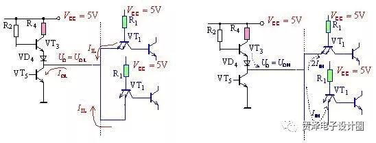
(a) sink current load (b) pull current load
Figure 18-2-3 Schematic diagram of sinking current and discharging current

(a) sinking current load characteristic curve (b) test circuit
Figure 18-2-4 Current sinking load characteristic curve and test circuit
When the output low level voltage value increases to the output low level maximum value as the sink current increases, the corresponding sink current value when uOL=UOLMAX is defined as the large value IOLMAX of the output low level current.
Different series of logic circuits, different types of integrated circuits in the same series, the specification of the maximum value of the output low level current IOLMAX in the national standard is often different. The more commonly used values ​​are as follows:
TTL Series IOLMAX=16mALSTTL74 Series IOLMAX=8mALSTTL54 Series IOLMAX=4mA
The fanout factor NO is a parameter describing the load capacity of an integrated circuit. Its definition is as follows: 18-2-1)
NO= IOLMAX / IILMAX
Where IOLMAX is the maximum allowable sink current, and IILMAX is the current that a load gate sinks into this stage.
The larger the No, the stronger the load capacity of the door. General product requirements require No ≥ 8.
When determining the fanout factor, it is important to calculate the current value correctly. For Figure 18-2-3, the input terminals of the logic gates connected later are connected in parallel. When the output is low, the IIL flowing out of the input of the logic gate is dependent on the current limit of R1, regardless of the number of parallel terminals. However, when the output is high, the direction of the current changes to flow into the input, and the multi-emitter of the subsequent logic gate input stage has two transistors in parallel. The inflow of IIH is doubled, depending on the number of parallel ends. For Figure 18-2-3, NOL=2, and NOH=3, the fanout factor may be different in both the output low level and the output high level. Since the value of IIL is much larger than the value of IIH, the main aspect of contradiction for integrated circuits is the low-level fan-out factor. Therefore, in general, we only need to consider the low-level fan-out factor.
Solid-state capacitors / Motor starting capacitors
Solid - state capacitors are all called: solid - state Aluminum Electrolytic Capacitors.It with the ordinary capacitance (that is, the liquid aluminum electrolytic capacitors) the biggest difference is that use different dielectric material, liquid aluminum capacitor dielectric material as the electrolyte, and solid-state capacitor dielectric material is conductive polymer materials.Solid-state Capacitors / Motor Starting Capacitors
Solid-state capacitors / Motor starting capacitors,Solid-State Capacitors,Solid-State Small Size Capacitors,Solid-State Low Impedance Capacitors,Long Life Solid-State Capacitors
YANGZHOU POSITIONING TECH CO., LTD. , https://www.cnfudatech.com