To understand rigidity, it's helpful to start with stiffness. Stiffness refers to a material or structure’s ability to resist elastic deformation when subjected to an external force. It reflects how difficult it is for a material or system to deform under stress. In the macroscopic elastic range, stiffness is represented as the proportional relationship between the applied force and the resulting displacement. This means that stiffness measures the amount of force needed to produce a unit of displacement. The inverse of stiffness is called compliance, which describes how much a material deforms under a unit of force.
Stiffness can be categorized into static and dynamic types. Static stiffness refers to the resistance to deformation under a constant load, while dynamic stiffness involves resistance during oscillatory or time-varying forces. For example, the stiffness (k) of a structure is defined by the formula k = P / δ, where P is the applied force and δ is the resulting deformation. Similarly, for rotational systems, the rotational stiffness is given by k = M / θ, where M is the applied torque and θ is the angular displacement.
In practical terms, materials like steel are considered stiff because they deform very little under external forces, whereas materials like rubber are flexible and deform significantly under the same load. This is why we say steel has high rigidity, while a rubber band has low rigidity or high flexibility.
In servo motor applications, couplings are used to connect the motor to the load, forming a rigid connection. On the other hand, timing belts or pulleys create a flexible connection. The rigidity of the motor shaft refers to its ability to resist external torque. This can be adjusted via the servo controller, allowing engineers to fine-tune the system’s response.
The mechanical stiffness of a servo motor directly impacts its response speed. Higher stiffness typically leads to faster responses, but if set too high, it can cause mechanical resonance—leading to instability. Therefore, most servo amplifiers include manual adjustments to optimize performance based on the system’s characteristics and experience.
In position mode, a servo system is considered rigid if a large force causes only a small deflection. This concept is closely related to the system’s response speed rather than just physical stiffness. From the controller’s perspective, stiffness is a combination of the speed loop, position loop, and integral time constants. These parameters determine how quickly the system reacts to changes.
Many modern servos, such as those from Panasonic and Mitsubishi, have automatic gain adjustment features, reducing the need for manual tuning. However, some domestic models require manual settings, which can be time-consuming and require expertise.
It’s important to note that in applications where fast positioning isn’t critical, a lower stiffness setting can still achieve acceptable accuracy, though with longer positioning times. A low stiffness might give the illusion of inaccuracy if the system is not properly tuned, even though the actual positioning is correct.
Inertia, on the other hand, refers to an object’s resistance to changes in motion. The moment of inertia measures how mass is distributed around an axis of rotation. When the load inertia exceeds ten times the motor’s rotor inertia, it is considered significant. This affects the overall stability and performance of the servo system.
The inertia of components like the lead screw and linear guide rail plays a crucial role in the system’s rigidity. With fixed gain settings, higher inertia increases the likelihood of motor vibration, while lower inertia reduces this risk. By using smaller diameter guides or screws, engineers can reduce the load inertia and improve system stability.
When selecting a servo system, it’s essential to consider not only torque and speed but also the inertia of the entire mechanical system converted to the motor shaft. Proper inertia matching ensures optimal performance, especially in applications requiring precise motion control.
During manual mode debugging, correctly setting the inertia ratio parameter is key to achieving the best performance of the system. So, what exactly is “inertia matching� It’s about balancing the system’s inertia so that the motor can respond efficiently without overloading or underperforming.
According to the basic law of motion: Torque required for the feed system equals the system’s moment of inertia multiplied by angular acceleration. Angular acceleration affects the system’s dynamic behavior. If angular acceleration is small, the controller takes longer to issue commands, leading to slower responses. This can impact processing accuracy.
Once the servo motor is selected, its maximum output remains constant. To maintain stable performance, the system’s moment of inertia should be kept as low as possible. The total inertia J consists of the motor’s rotor inertia (JM) and the load inertia (JL) converted to the motor shaft. JL varies depending on the load, such as workpieces, fixtures, and moving parts. To minimize the variation in J, it’s better to keep JL as a small percentage of JM.
This is essentially what “inertia matching†means. Servo motors with low inertia offer better braking performance, faster acceleration and deceleration, and are ideal for high-speed, light-load applications. Motors with higher inertia are more suitable for heavy loads and systems requiring stability, such as machine tools or circular motion mechanisms.
Therefore, both rigidity and inertia must be carefully balanced. Too much or too little rigidity can affect the system’s performance, and similar considerations apply to inertia. Adjustments are usually made through the controller’s gain settings, ensuring the system operates smoothly and efficiently.
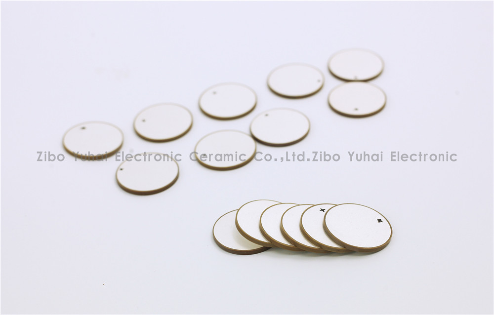
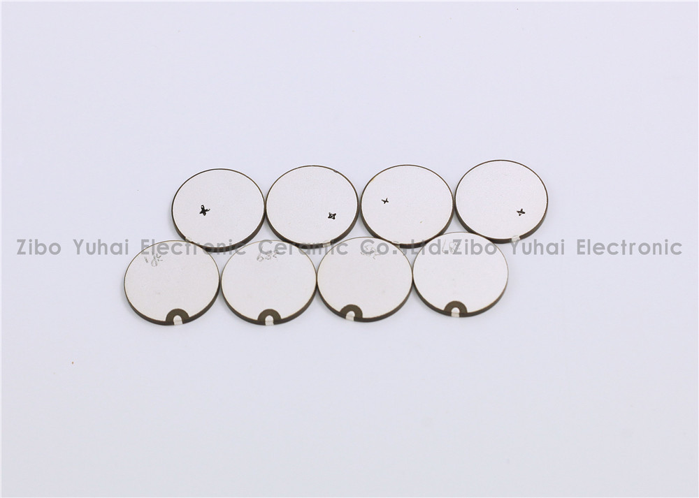
Piezoelectric Discs For Flowmeter Sensor
Piezoelectric ceramic disc
Quick delivery
High performance
Application: flow meter measurement
There are many kinds of USF used in closed pipeline according to the measuring principle, and the most commonly used are propagation time method and Doppler method. Among them, time difference ultrasonic flowmeter is used to measure fluid flow by the principle that the time difference of sound wave propagating downstream and countercurrent is proportional to the velocity of fluid flow. It is widely used in raw water measurement of rivers, rivers and reservoirs, process flow detection of petrochemical products, water consumption measurement of production process and other fields. According to practical application, time-difference ultrasonic flowmeter can be divided into portable time-difference ultrasonic flowmeter, fixed time-difference ultrasonic flowmeter and time-difference gas ultrasonic flowmeter.
Ultrasonic flow-meters use at least two transducers aligned so that ultrasonic pulses travel across the flow of liquid or gas in a pipe at a known angle to the flow.
Technical data:
Electromechanical coupling coefficient Kp: > 0.62
Dielectric Loss tg δ: <2%
Nominal Piezo discs for ultrasonic flowmeter:
OD14.2*1MHz PZT-51
OD14.6*1MHz PZT-51
OD15*1MHz PSnN-5
OD15*2MHz PSnN-5
OD20*1MHz PSnN-5OD20*2MHz PSnN-5
OD15*1MHz PZT-51
OD15*2MHz PZT-51
OD20*1MHz PZT-51OD20*2MHz PZT-51
Size, Frequency and Electrode on request.


Piezoelectric Ceramic Disc,Piezoelectric Disk Flow Meter,Piezoelectric Flow Sensor,Piezo Discs Flowmeter
Zibo Yuhai Electronic Ceramic Co., Ltd. , https://www.yhpiezo.com