Abstract: Introduce the performance characteristics of the most popular monolithic RF transceiver chip nRF24E1 and the special chip TMC2023 with related computing functions; elaborate the related computing theory in signal processing and combine the theory with the circuit based on the above two chips. , Used in automobile anti-collision systems to enhance the capabilities of automobile anti-collision systems.
introduction
With the development of the times and the progress of society, more and more cars have entered ordinary people's families. Despite the continuous improvement of highway conditions, the current situation of car congestion on the highway is still inevitable. In addition, the speed of vehicles is gradually increasing, and vicious traffic accidents occur all the time, causing huge loss of life and property to people and society.
figure 1
Automobile anti-collision system is a detection device that can send an audio-visual warning signal to the driver in advance. It is usually installed on a car and can detect pedestrians, vehicles or surrounding obstacles that are trying to approach the body; it can send a signal to the driver and occupant in advance of the danger of a crash, prompting the driver to even take the driver to take emergency measures to deal with special dangers and avoid losses . At present, although all countries are researching anti-collision systems, how to better solve the problem of false alarms has always plagued relevant workers. International researchers have reached consensus through extensive experimental research. If the anti-collision system wants to effectively solve the above problems, it must have the following functions, namely:
â‘ Must have the ability to measure angle. The azimuth information of the target is essential for removing false alarms.
â‘¡ Design a complex transmitted signal that is easy to generate and has strong anti-interference performance, cooperate with real-time and efficient signal processing and target detection algorithm to remove false alarms.
Only when the above two points are closely combined can the reliability of the automobile anti-collision system be guaranteed.
1 Introduction of chip features 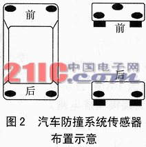
(1) Related arithmetic chip TMC2032
TMC2032 is a new type of all-digital correlator circuit, whose related word length and related threshold are programmable. The chip is a monolithic 64-bit CMOS all-digital related large-scale integrated circuit launched by the US TRW in recent years. There are three independent clocked eight-bit shift registers inside: random data register A, local code register B and mask code register M; one seven-bit BCD code output, and compared with the preset threshold value in the comparator . If the correlation value is greater than or equal to the threshold value, the flag bit changes from low to high. Due to the use of advanced high CMOS production technology, the parallel correlation rate is up to 30Mbps or more; it can be widely used for synchronization, matched filtering, error detection, recording, and barcode recognition, especially for radar signal recognition.
(2) RF transceiver chip nRF24E1
nRF24E1 is a wireless radio frequency transceiver chip with working frequency up to 2.4GHz. Built-in 8051 compatible microprocessor and 10-bit 9-input A / D converter, can work stably under voltage between 1.9 ~ 3.6V. There is also a voltage regulator and VDD voltage monitoring inside, the channel shape time is less than 200μs, the data rate is 1Mbps, and no external SAW filter is needed. nRF24E1 is the world's first 2.4GHz universal, complete and low-cost radio frequency system-on-chip that was first introduced in the world. The wireless transceiver part has the same function as nRF2401. This function is started by an external parallel port and an external SPI. Each signal to be sent can be programmed as an interrupt to the processor, or implemented through the GPIO port. nRF24E1 is a chip that can realize wireless communication in the world's public frequency range (2.4 ~ 2.5GHz). The transceiver contains a fully integrated frequency divider, amplifier, regulator and 2 transceiver units. The output energy, frequency band and other RF parameters can be easily programmed and adjusted through the RF register. In the transmission mode, the current consumption is only 10.5mA; in the reception mode, only 18mA, so the power consumption is quite low.
2 System structure
The entire information collection system consists of 5 sets of radio frequency transmitting and receiving devices, and the basic circuit of each transmitting and receiving part is the same. Figure 1 is the core circuit of RF transceiver. These 5 sets of transceiver systems are connected to the DSP central processor. The central processor is responsible for calculating the data they pass over, and then makes decisions based on actual conditions. 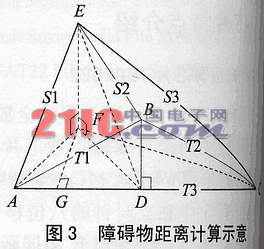
The structure of each set of transmitter and receiver is shown in Figure 1. First, the high-frequency electromagnetic wave is emitted by the radio frequency transmitting circuit with nRF24E1 as the core. Before sending, the modulated signal sent by the relevant arithmetic chip TMC2032 modulates it, thereby generating a radio frequency signal different from other radio frequency transceiver units for Fully prepared. In order for the electromagnetic wave signal to have a sufficiently long propagation distance, it is also necessary to amplify the modulated signal. The circuit that accomplishes this function is the power amplifier circuit. Finally, such a signal is transmitted into the air.
When the emitted electromagnetic wave encounters an obstacle and returns, it must first be identified by the relevant arithmetic chip TMC2032: if it is sent by the transmitting part of the same group, it is received, and this signal is further transmitted to the radio frequency receiving part. The phase shift generated by the receiving chip through the propagation of such electromagnetic waves in the air calculates the time it takes to propagate, and then calculates the distance between the obstacle and the set of transceivers. Finally, this distance information is sent to the central processor. The central processing single-chip microcomputer must simultaneously calculate the distance information transmitted from the five groups of RF transceiver units, and obtain the three-dimensional azimuth distance between the measured obstacle and the vehicle. At this point, the information collection of obstacles has basically been completed, and the rest is to pass this comprehensive information to a more advanced central processor to let it make the final decision.
3 Layout plan and calculation example of transceiver unit
As the car is traveling, it is necessary to be able to determine the spatial three-dimensional orientation of the obstacle in front of the car relative to the car, in order to avoid the front, back, left, right, and top obstacles; The distance between front, back and left and right is sufficient. Therefore, three RF transceiver systems are installed in front of the vehicle, and the three transceiver systems are distributed in a triangle perpendicular to the horizontal plane; the rear are installed with two RF transceiver systems, which are horizontally distributed. The installation of the entire transceiver system is shown in Figure 2. In Figure 3, a simple process of calculating the distance of obstacles using the RF transceiver system is given.
It is known that the calculation of the distance of a three-dimensional obstacle composed of S1, S2, S3, T1, T2, and T3 is shown in FIG. 3. Among them, three points A, B and C represent the three ultrasonic sensors installed in front of the car, point E represents the obstacle; then EF represents the distance from point E to the horizontal plane, FG represents the distance from the obstacle to the front, and AG represents the obstacle The distance to the side of the car. What we require is three straight lines of EF, FG and AG. The solution is as follows:
Make BD⊥AC in △ ABC, connect ED and FD, you can find in △ ABC
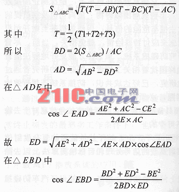
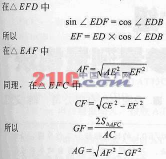
Substitute the known numbers S1, S2, S3, T1, T2, and T3 respectively to obtain the three distance values.
4 Related algorithms
With the wide application of radio frequency technology in daily life, people gradually find that there are certain defects in radio frequency ranging: â‘ the effective distance is relatively short, and the increase of the transmission power to increase the measurement distance is limited; â‘¡ the accuracy of the distance measurement is mainly Depending on the signal-to-noise ratio of the echo signal, under a certain signal-to-noise ratio, it is also very limited to improve the measurement accuracy only by increasing the gain of the preamplifier circuit. In order to solve the above problems, this automobile collision avoidance system envisages a radio frequency transmission and reception system based on pseudo-code modulation.
The random process is white noise, and its instantaneous values ​​follow a Gaussian distribution (normal distribution). Its power spectral density is uniform over a wide frequency band, and the autocorrelation function has the shape of a delta function. Although the pseudo-random code has only two levels, it has a correlation characteristic similar to white noise, except that its amplitude probability distribution no longer follows the Gaussian distribution. Therefore, the pseudo-random codes can be described by the balance characteristics, run-length characteristics and related characteristics of pseudo-random sequences. Pseudo-random coding is realized by logical operation, and the autocorrelation function of the signal satisfies:
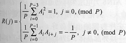
It can be seen that when P is large enough, the autocorrelation coefficient has a sharp two-level characteristic, close to the δ function. In ultrasonic ranging based on pseudo-random codes, it is precisely the sharp characteristics of the auto-correlation function of pseudo codes to measure the delay between the transmitted code and the received code, thereby improving the measurement accuracy. The m-sequence pseudo-random code is a sequence with the longest period generated by the linear shift register. Because of its excellent correlation characteristics and easy generation, it has been widely used.
According to the definition of related functions, set 2 time functions X1 (t), X2 (t), then
![]()
The autocorrelation function called X1 (t);

The cross-correlation function called X1 (t) and X2 (t).
There are two types of problems in signal detection theory: one is to detect the signal, that is, to judge whether there is a signal based on the received mixed signal (signal plus noise or pure noise); Based on the presence or absence of the signal, some parameters (such as amplitude, phase, frequency, pulse amplitude, etc.) or waveform of the signal are estimated. In order to improve anti-interference, it is necessary to find the best method for receiving signals under interference conditions. Since the correlation function of the periodic signal is still a periodic function, the correlation function of the interference noise is the delta function. Based on these differences, the correlator can be used to detect periodic signals mixed in noise interference. This method of using the difference in time domain characteristics to detect signals is called the correlation receiving method. According to different reference signals, it is divided into auto-correlation receiving method and cross-correlation receiving method. The autocorrelation reception method is to use the autocorrelator to calculate the autocorrelation function when the input waveform (or data) cannot be determined; the crosscorrelation reception method is to use the correlator to input The waveform (or data) and the local signal are cross-correlation functions. The reference signal in this design is a local code, so the cross-correlation receiving method is used. In the radio frequency ranging system, not only the presence or absence of the echo signal must be detected, but also the delay time of the echo signal and the transmitted signal must be accurately measured. In this way, we can accurately know the time it takes for radio waves to propagate, and then calculate the distance between the obstacle and the car.
5 Summary
This article successfully uses advanced radio frequency technology and stable and reliable related algorithms to make the car have a strong anti-collision ability. The above overall design scheme has been implemented on the experimental car, and to a certain extent, it can solve the two key problems that have always plagued related workers in the aforementioned automobile collision avoidance system. That is, it already has a more sensitive angle measurement capability and a stronger anti-jamming capability, so that the car can have a stronger anti-collision capability. Nevertheless, because the life of the car is related to the safety of human life, its performance needs to be further improved to enhance the absolute safety of the entire system, and then promote it.
Street Lighting Poles,Street Lamp Post,Street Light Post,Street Lamp Pole
Jiangsu Baojuhe Science and Technology Co.,Ltd. , http://www.galvanizedsteelpole.com