1 Introduction
The frequency converter is of great significance in energy conservation and power environmental protection. The motor drive is a large electric energy consumer, which consumes about 65% of the country's power generation. In the past 30 years, the frequency conversion speed regulation has been in the work of steel, metallurgy, petroleum, chemical, electric power, etc. Widely used, other household appliances such as inverter refrigerators, inverter washing machines, inverter microwave ovens, etc. have also appeared one after another, so designing reliable and high-performance inverter power supply is particularly important.
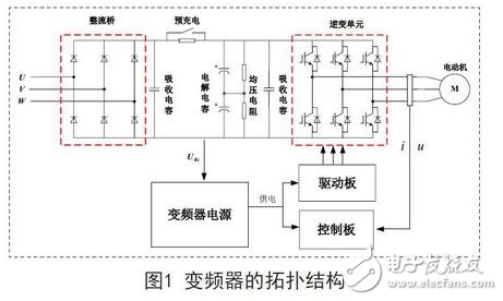
The frequency conversion technology has been widely used, and the reliable and stable operation of the inverter determines the performance index of the inverter. As the basic hardware, the efficient and reliable operation of the inverter power supply is very important. As shown in Figure 1, the topology of the inverter is mainly composed of a rectifying unit, a pre-charging circuit, a braking unit and an inverter unit. As can be seen from the figure, the inverter power supply provides DC power to the driving circuit and the control circuit, and the driving circuit The inverter unit is provided with a driving pulse with a strong driving capability and a fast response speed, so it is particularly important to design an efficient and reliable inverter power supply hardware.
2. Power soft switching technology and circuit principle
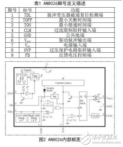
AN8026 is a flyback single-ended output RCC quasi-resonant soft-switch drive controller developed by Panasonic. It is packaged in a SIP 9-pin package. The definition of each pin is shown in Table 1. The internal block diagram is shown in Figure 2. as follows:
· The supply voltage is from the lower limit of 8.6V to the upper limit of 34V;
· The output pulse is a single-ended totem pole drive pulse;
·The output drive current is +1A, which directly drives the M0SFET tube;
· Start current is 8uA, reducing the power consumption of the startup resistor;
· Built-in weekly control over current protection circuit;
· Input undervoltage 8.6V protection circuit with built-in hysteresis characteristic;
· Overvoltage protection circuit of external voltage regulator.
The limit parameters of AN8026 are shown in Table 2, and Figure 3 is the circuit schematic of AN8026. The soft switching power supply is mainly composed of a control chip AN8026, a MOSFET K2225, a TL431, a pulse transformer TR1, and the like. VCC is powered by the DC bus through the starting resistors R1, R3, R5, and R6. The input DC link voltage level can adjust the resistance of the starting resistor. When the starting voltage is reached, the converter starts to work. After that, the control chip is operated by the vice. Side +18V auxiliary winding power supply.
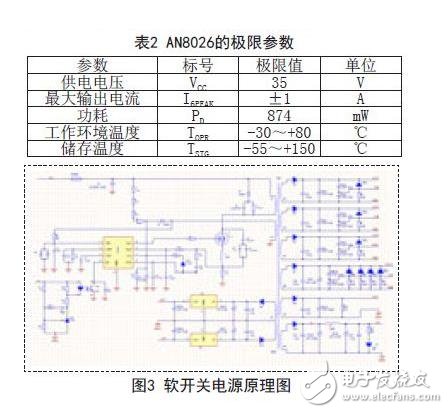
R8 will limit the induced pulse of the TR1 auxiliary winding, diode D6 is clamped negatively, and a positive pulse of 2.8V is sent to the first pin to be used as the magnetic flux reset detection of TR1, which can prevent the switch tube from being turned on when the TR1 magnetic energy is not released. The generated inrush current ensures the stability of the output voltage; the external pin C10 and R14 of the second pin set the minimum off time, C10 sets the minimum on time; the periphery of the 4th pin uses R15 as the source current sensor of the switch, which is proportional to The peak current of the switch current; the overvoltage protection of the 8th pin is sampled from the Vcc terminal by the Zener diode ZD4, so that the starting working voltage does not exceed the upper limit of 34V, the DZ selects the 22V voltage regulator tube, and at the same time, the output voltage can be output when the drive pulse is out of control. Protection; In order to prevent the start-up voltage of the AN8026 from starting before the transient voltage exceeds 28V, the circuit can not be activated, and the C13 is used to absorb the instantaneous over-pressure bee.
This display is a flat monitor, with built-in video decoding board or networking video decoding board, it can display preset text/photo/video/audios or display it online. This display is ideal for promotion in stores and advertisement/information display in publics. Sizes from 7'' to 42'', landscape and portrait display mode are available. The monitor is with standard VESA holes on the back, suit for pole mounting, wall mounting and ceiling hang. High bright and weather-proof displays are also available.
Broadcast Monitor,Signage Monitor,Digital Signage Monitor,Digital Signage Screen
Shenzhen Hengstar Technology Co., Ltd. , https://www.angeltondal.com